POLY555 Synth
I made a new Oskitone synth: the POLY555!
It's an analog, 20 note polyphonic, square wave synthesizer based on the 555 timer chip. The enclosure and keys are 3D-printed, its models were programmed in OpenSCAD, and its PCB was designed in Kicad.
A little history
The monophonic (one note at a time) OKAY synths I made a couple years ago also used the 555 timer as their oscillator, as a sort of homage to the ubiquitous chip's long history within the electronics community. When I showed one to folks in the scene, "the best 555 synth ever" was an easy, understandable pitch.
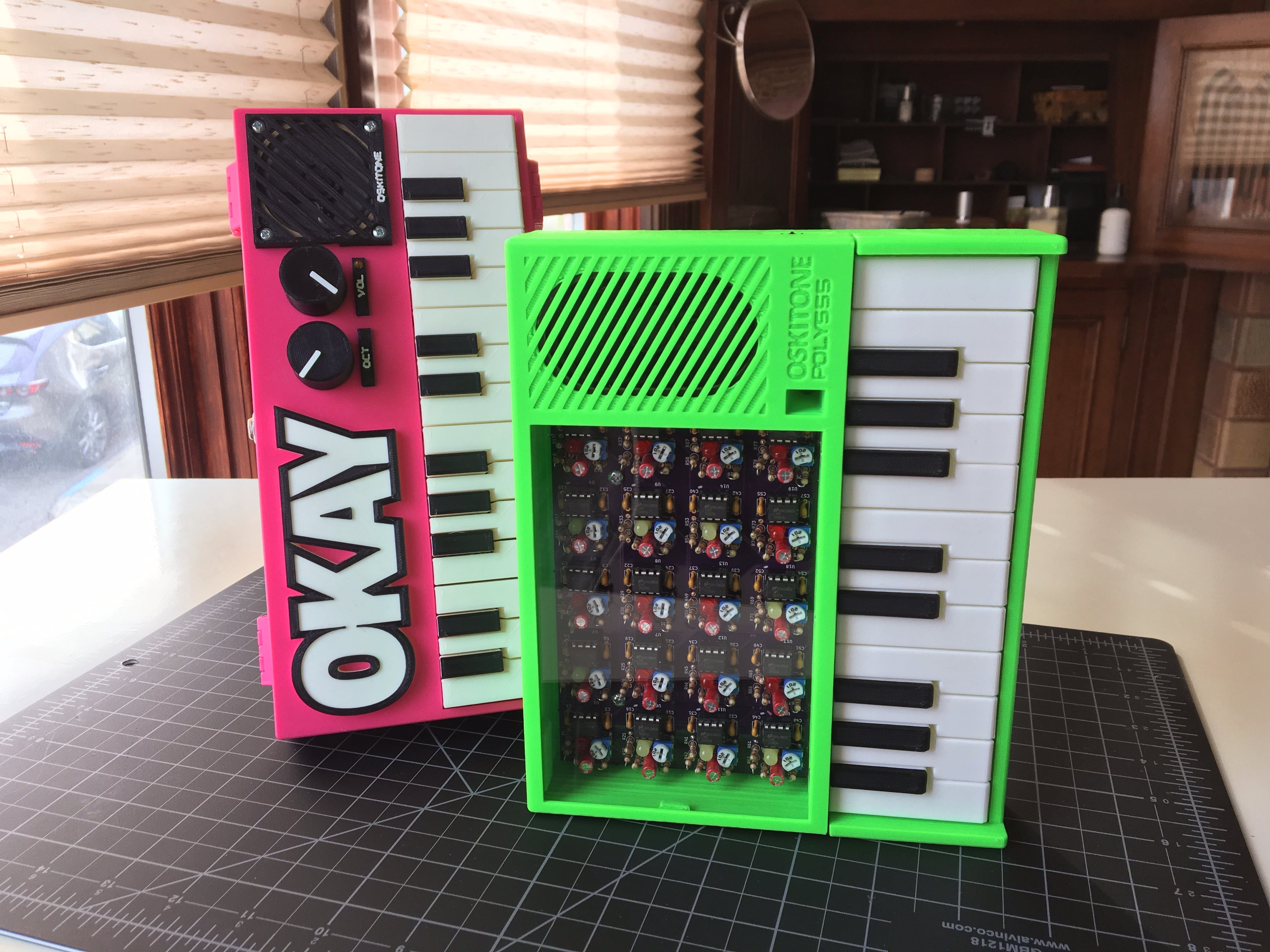
But the first question I always got was "How can it play more than one note?". To that I'd pop the hood and explain that since it has only one 555 to make one oscillator to make one note, to have more notes and still use the 555 I'd need... more 555s!
And while there are more economical ways to get analog polyphony (at the least, the 556 immediately comes to mind), I kept with discrete 555s because I thought it'd be fun to take this train of thought to its logical, if inconvenient!, extreme.
(I consider the POLY555 to be a spiritual successor to the OKAYs, which I haven't abandoned yet but absolutely need to give some TLC...)
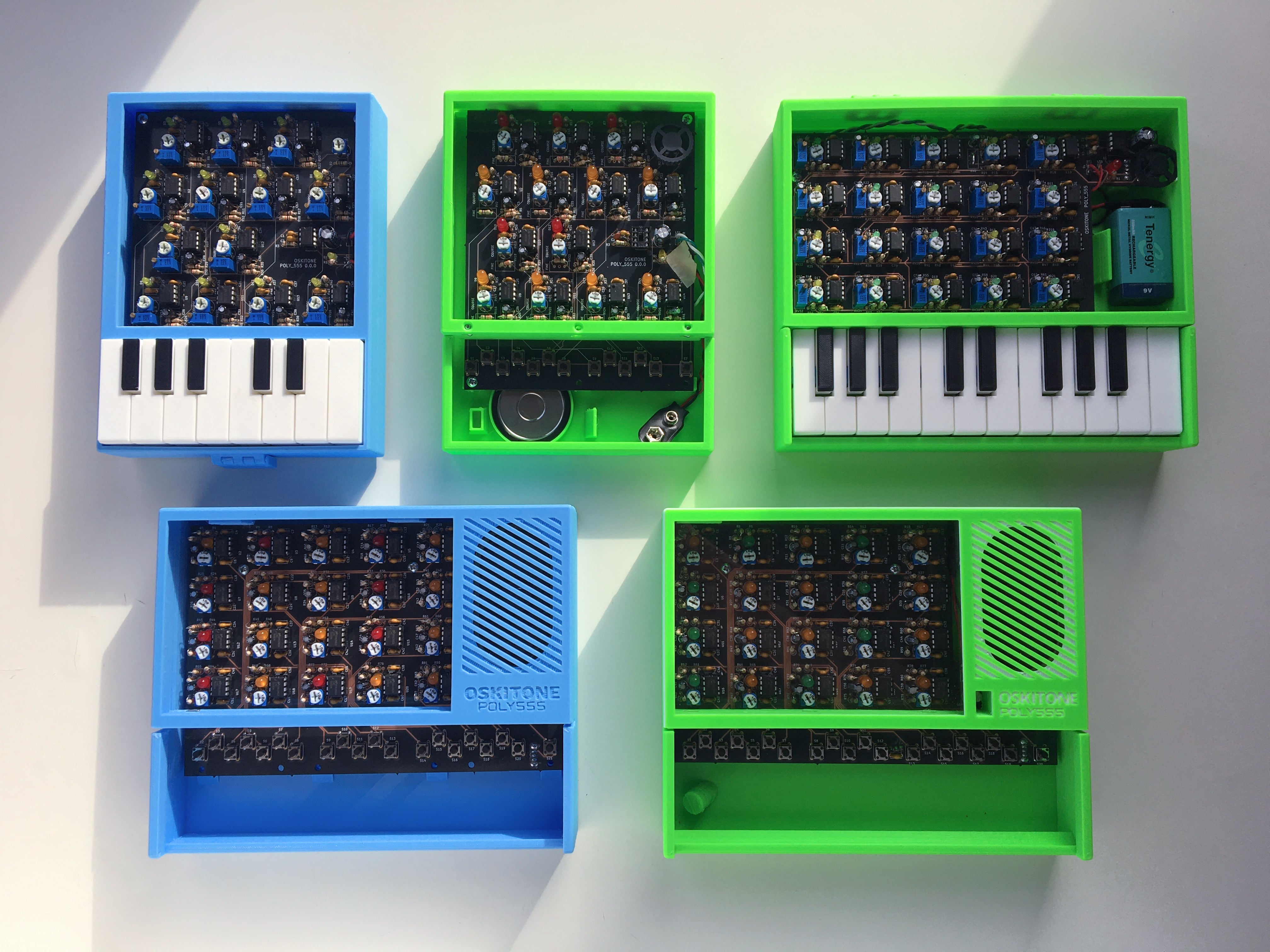
Features
|
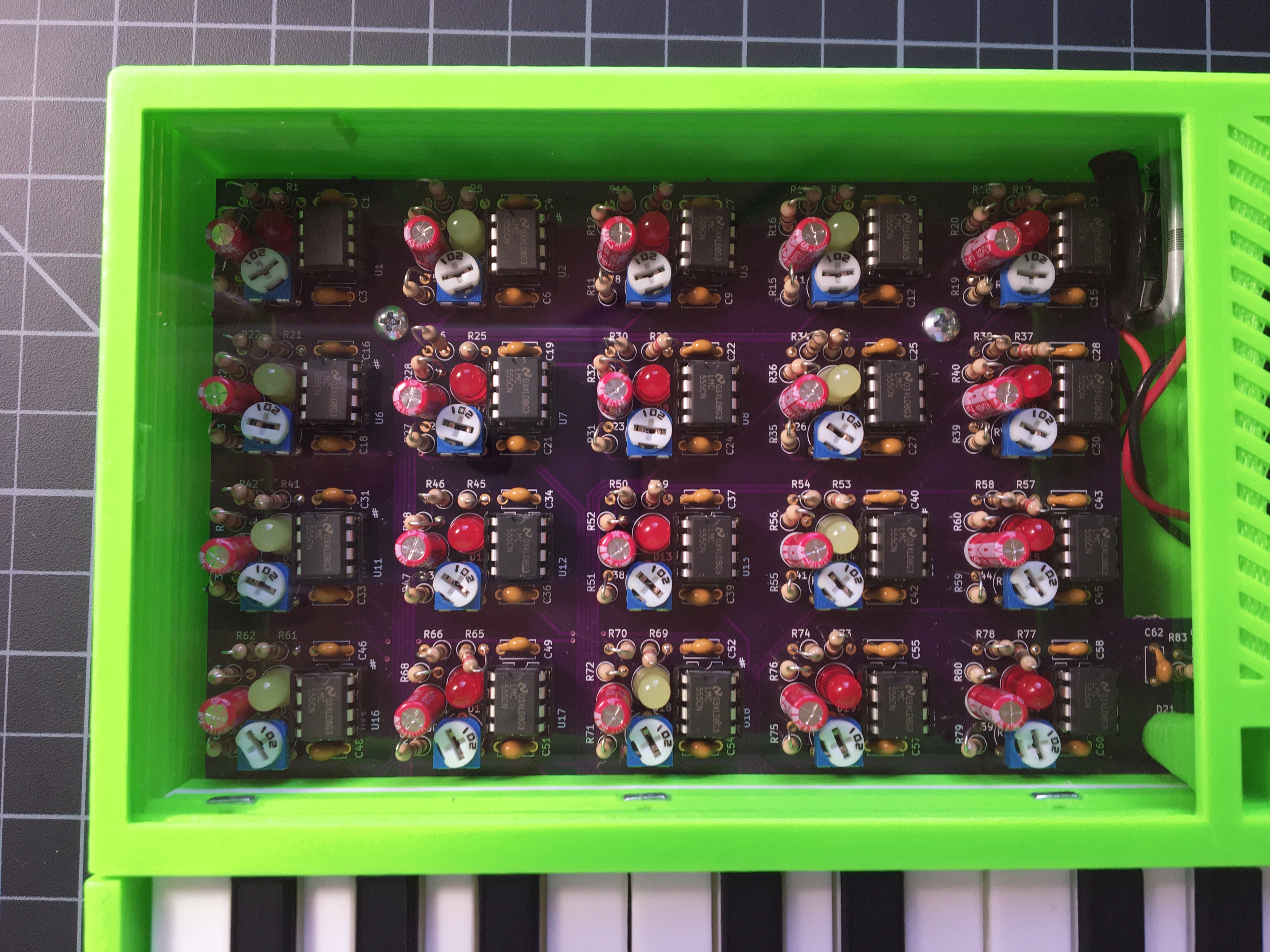
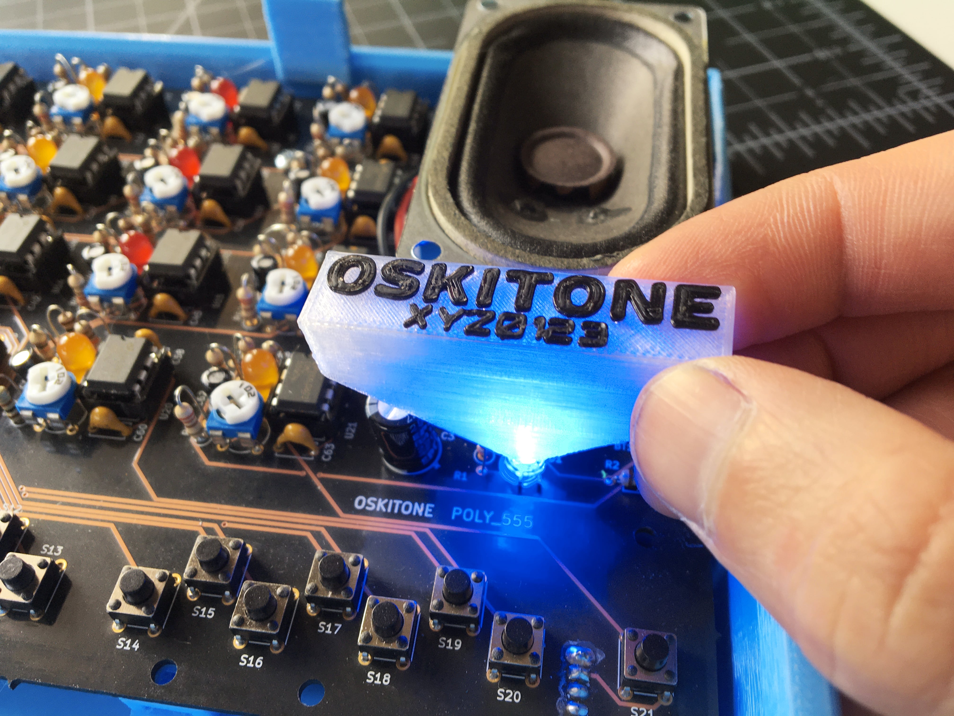
Exposed circuitry Obviously, right?! The 20 555 timer circuits are lovingly displayed in all their glory beneath a piece of plexiglass to protect them from dust. Each circuit also has an LED that lights up when it's supplied power. BTW, I chose 20 and picked their notes so they'd line up nicely in a grid! |
|
Thumbwheel volume control Just like an old Walkman, volume is controlled by a small wheel on the side. Instead of using a thumbwheel potentiometer, the wheel is 3D-printed and mounts to a pot identical to the timers’ tuners. |
|
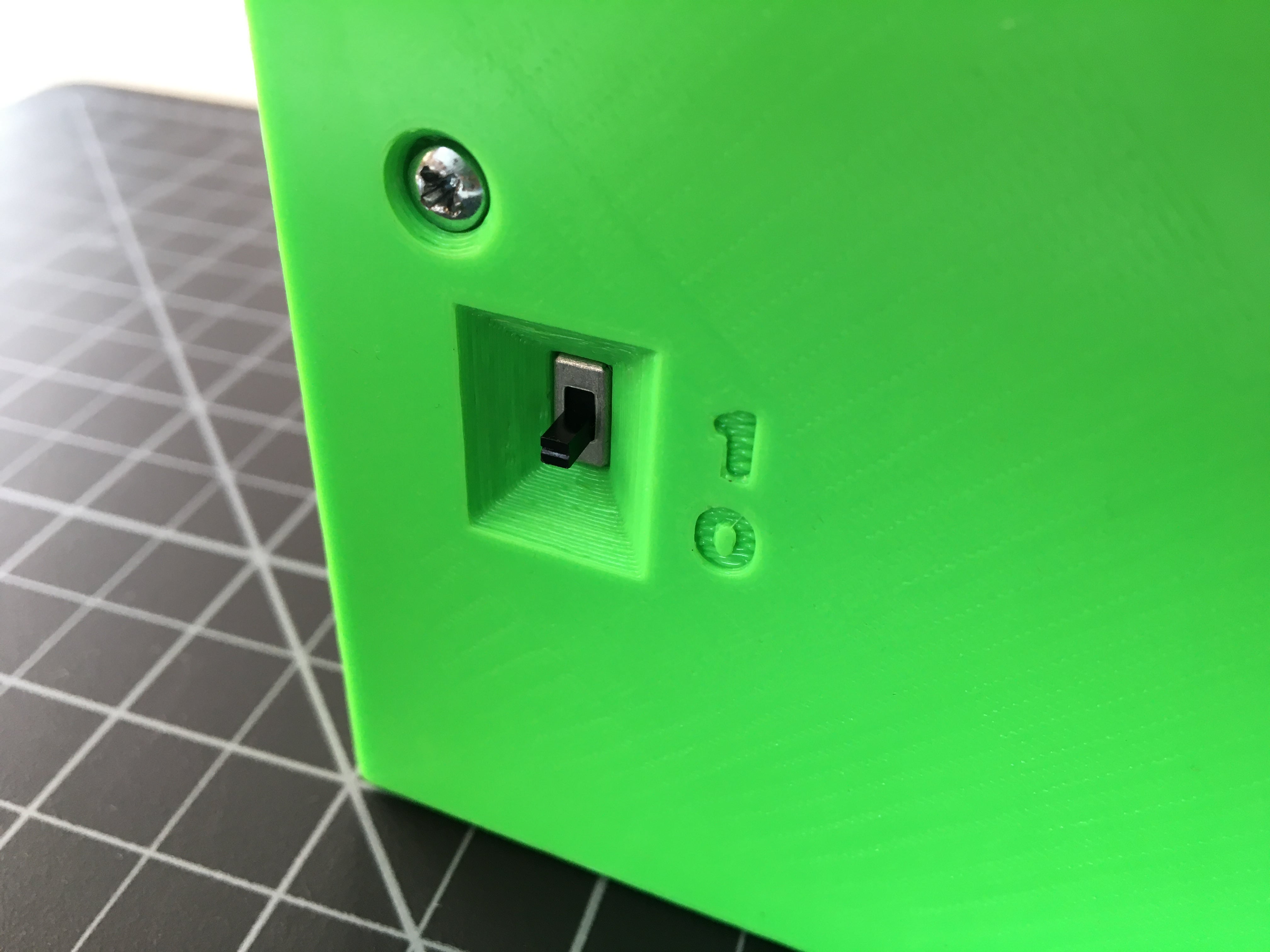
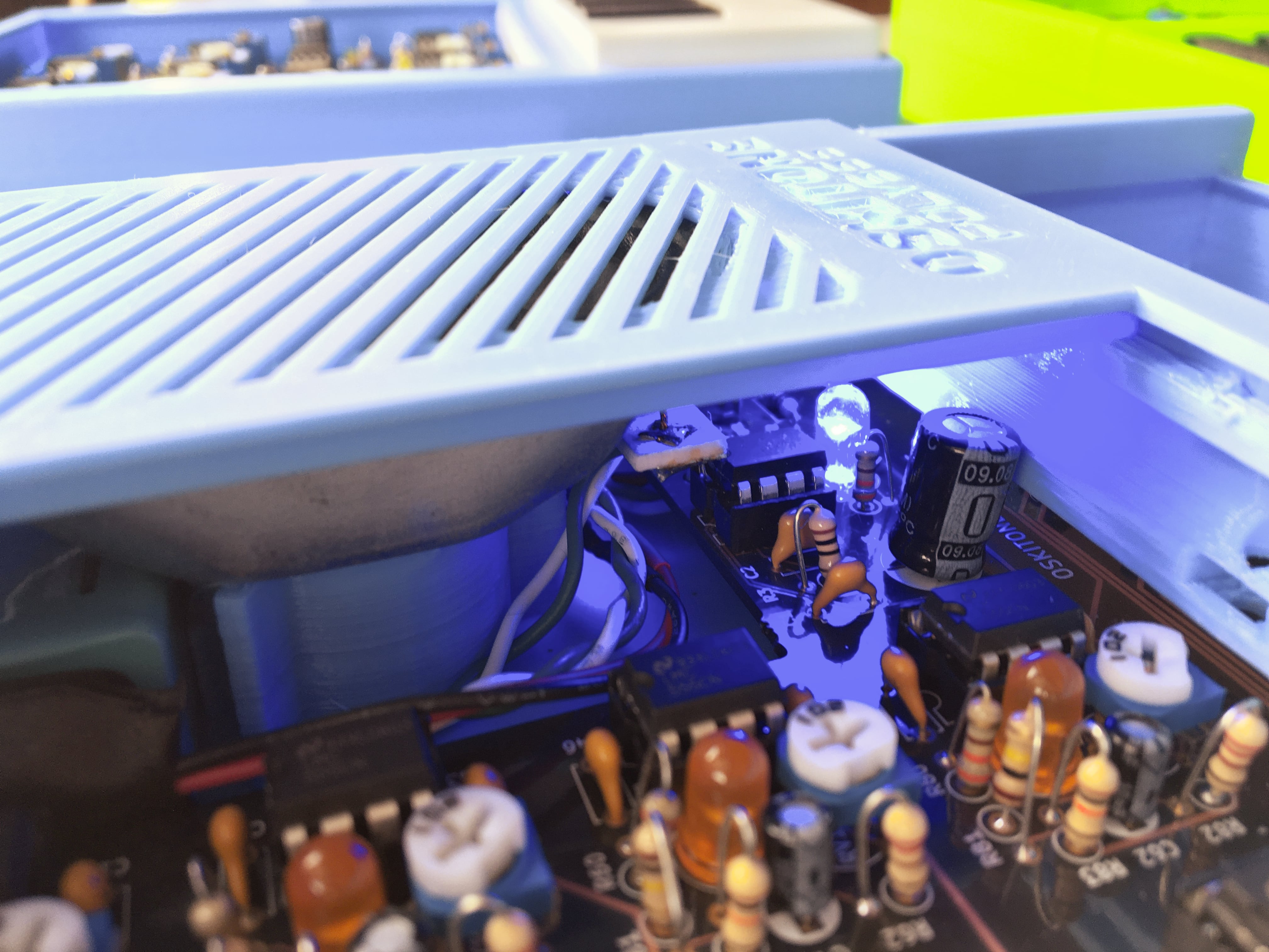
Power switch on bottom The power switch is similarly hidden away in a recessed cavity on the bottom of the enclosure with engraved binary labels. |
|
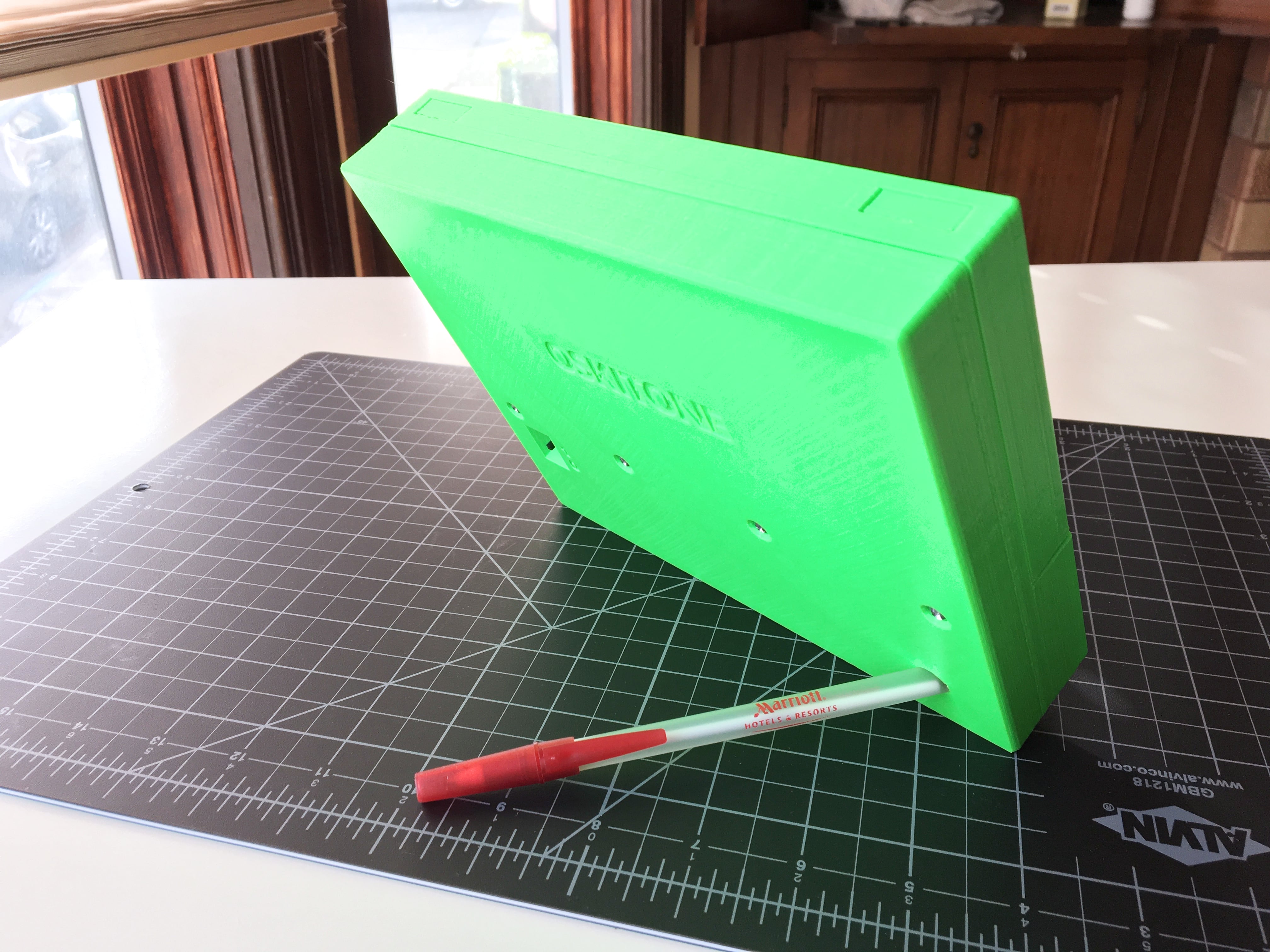
Pencil stand Jam a writing utensil in there to prop it up like a picture frame. Admire it! It's cool! |
How does it work
Schematic

From left to right:
- A sliding power switch connects the 9v battery's power to an on/off indicator LED, a 7805 voltage regulator, and a 386 amplifier.
- Regulated 5v is distributed across 20 tactile switch buttons, each of which is connected to a corresponding timer circuit, seen below.
- Those timers' outputs bus to a standard linear trimmer pot tricked into having a logarithm sweep, before going to the 386 amp's input.
- The 386 drives our speaker!
Timer circuit
All 20 555 circuits share the same circuit but have unique component IDs.

Again, from left to right:
- An LED puts on a little light show
- C1 is a bypass cap for stability
- This 555 circuit is called an astable multivibrator (oscillator) and is modified to have a 50/50 duty cycle... in other words, a square wave!
- The oscillator's frequency is determined by the C2 cap and the resistors R3 and RV1. RV1 is the 1k trimmer potentiometer for tuning.
- The chip's output passes through a "mixing" 10k resistor before leaving. This prevents the 555s from "sinking" each other, which would sound more like modulation (like, a lower frequency superseding a higher one) than mixing together harmoniously.
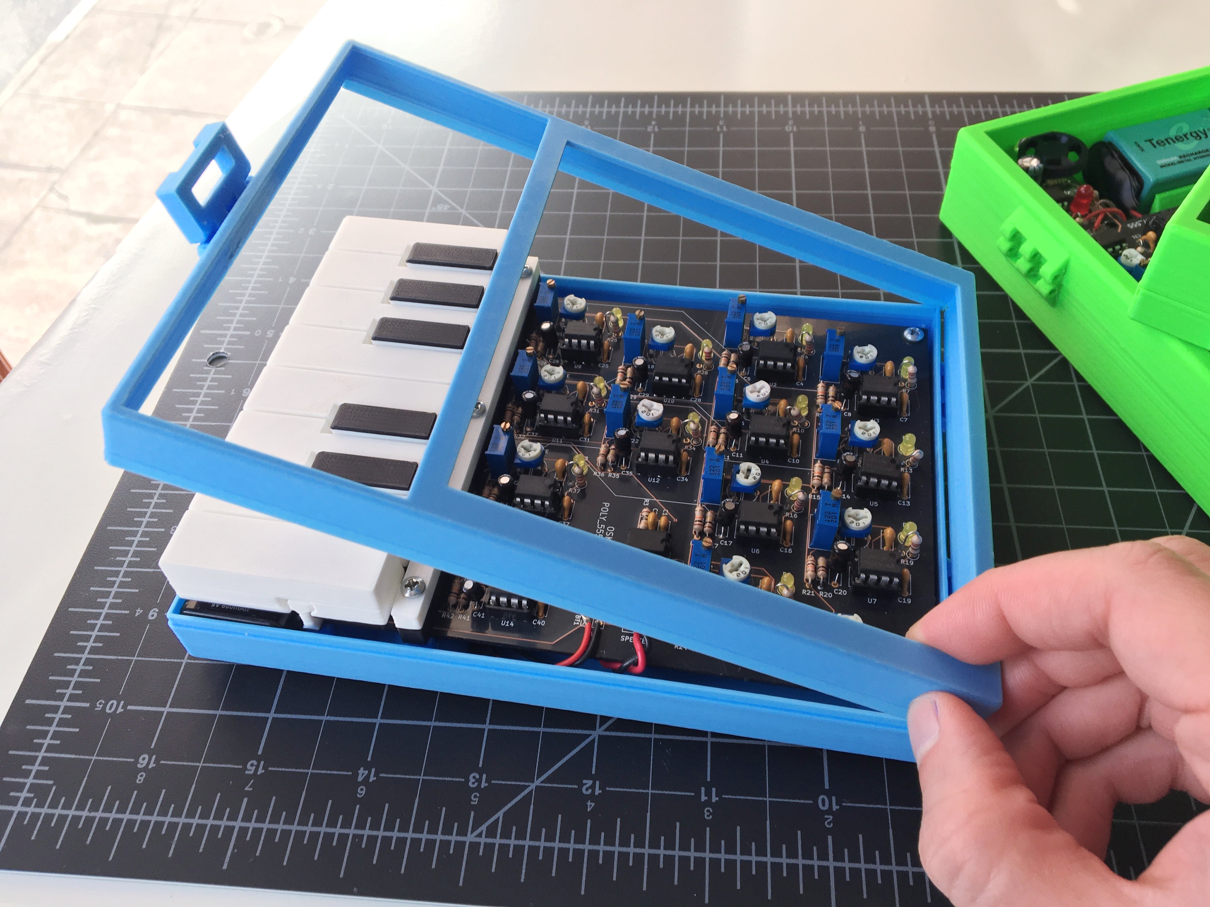
3D-printed parts
Outside of the electronics and plexiglass, the rest of the POLY555 is 3D-printed.

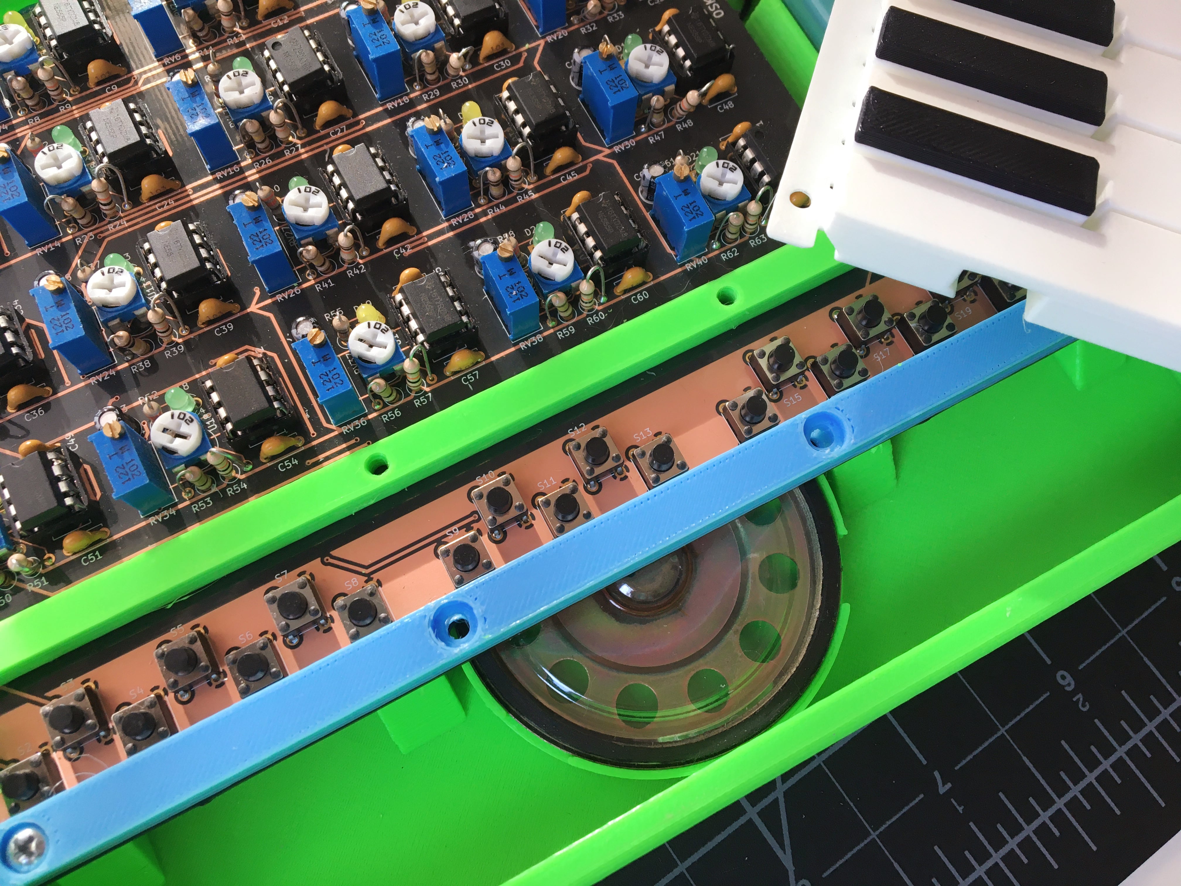
- Enclosure bottom
- Mounting rail for the keys to rest on
- Keys
- Volume wheel
- Enclosure top
Design for Manufacturing
Per usual with 3D-printed stuff, there are various tricks to get it to print nicely:
- Floating screw holes don’t have supports or the sacrificial bridge technique I previously wrote about. Instead, the cavity is first laid out as short, increasingly tighter rectangles, and the final cylinder cavity sits on that. Cool trick: it's an OpenSCAD module.
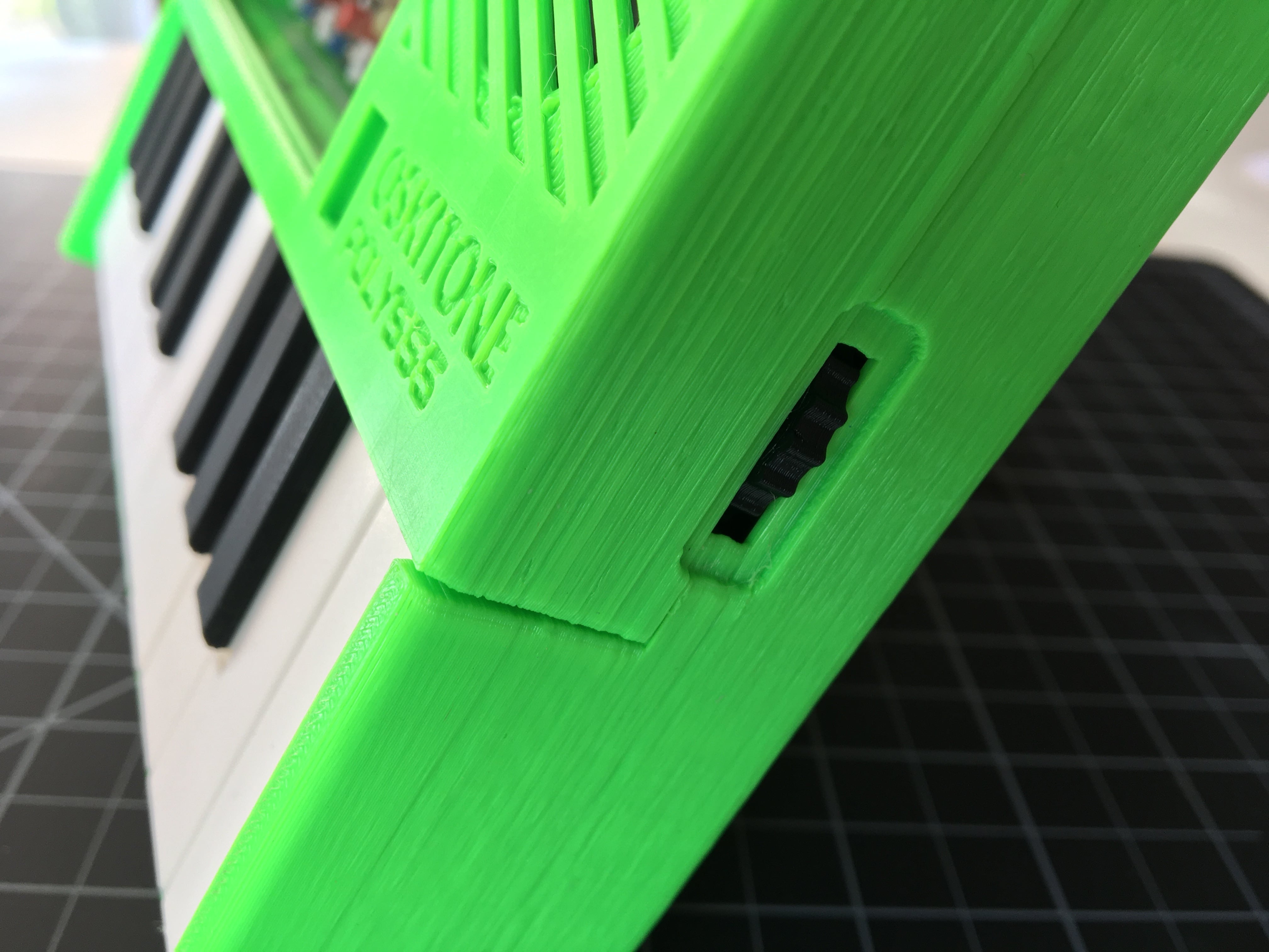
- Wherever possible, 45 degree angles are used to obviate supports: the key endstop, on/off switch exposure, volume wheel brace.
- And where right angles won't work and supports can’t be avoided, they're baked into the models themselves so folks at home don’t have to have their slicer do it: plexiglass window pane supports, enclosure hitches
- Exported STLs are oriented on the bed how they ought to be printed, with help from a shell script.
- The engraved "OSKITONE" and "POLY555" enclosure texts are 3D-printed with the text side down. A chamfer helps to alleviate some of the "elephant foot" that happens on the a print's first few layers.
Lessons learned from the OKAY
Better tuning
The POLY555 is both easier to tune and stays in tune longer than the OKAYs. Here're the OKAY 2's tuners on the key's flip side:
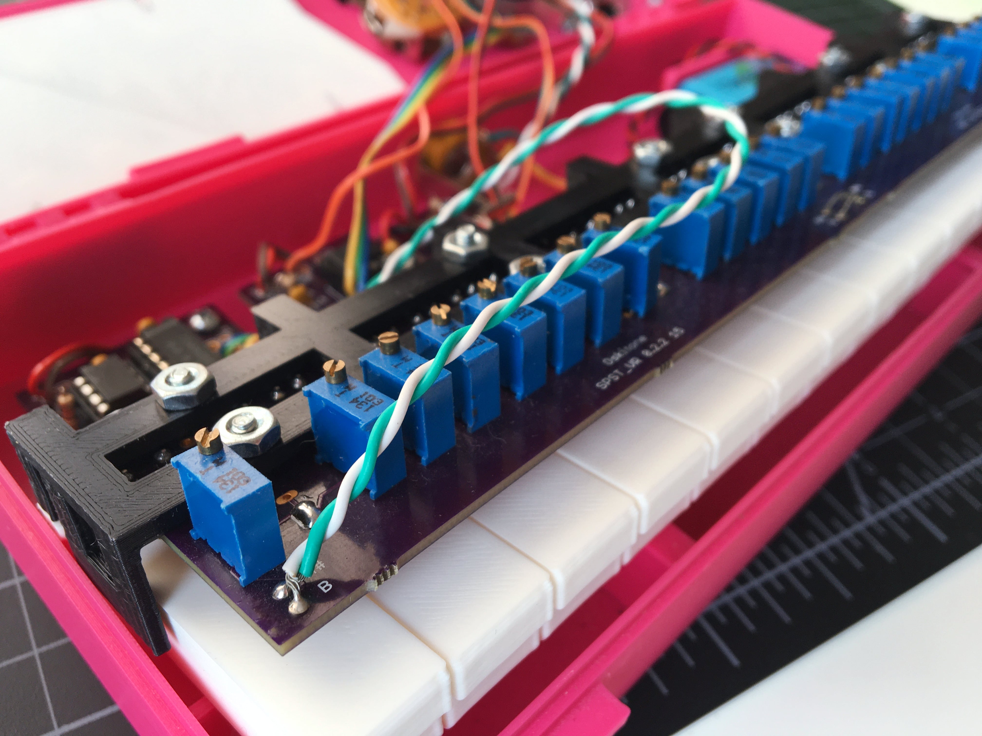
- That PCB is a resistor ladder. The further left on the keyboard the user plays, the more the resistance from the ladder, and the lower the note. So if one pot strayed out of tune, all the notes below it would too.
- The pots have 20 turns, which is great for high precision but painful on the wrist
- Should any of the buttons start to fail and introduce their own resistance, that gets added, causing an accidental vibrato.
- The 555s are sensitive to voltage changes. As the battery runs low, so do the frequencies.
All of that is fixed with the POLY555, where the tuning pots are independant and need less turning, the power buttons are separate from the tuning paths, and a regulator ensures constant voltage.
Hopefully easier to put together
Believe it or not, I think the POLY555 is easier (or at least more straightforward) to solder than the OKAY. Here's the inside of the OKAY 2 again for reference:
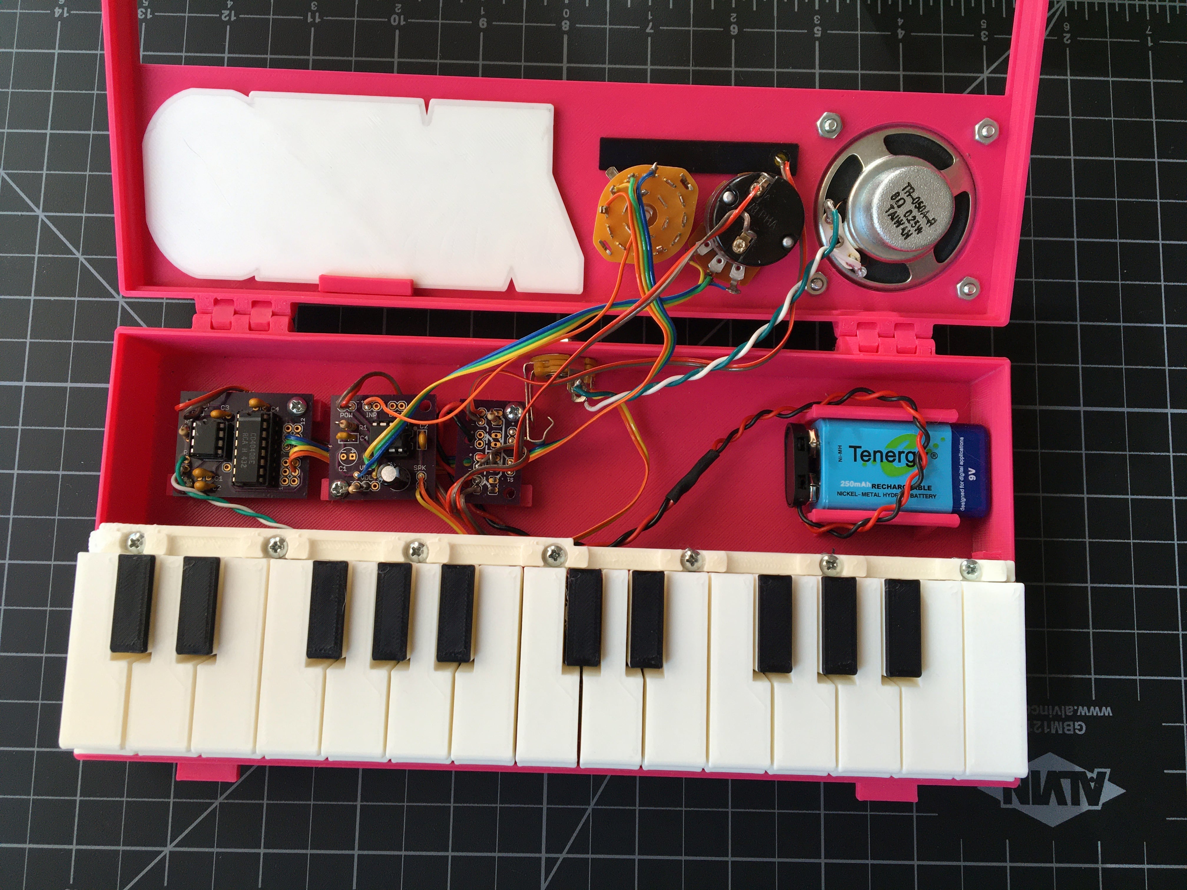
- Multiple PCBs connected with ribbon cable
- "Floating" components that don't mount to the PCB and also require wiring
- Some component footprints aren't actually the right size and require bending leads... yikes!
- Optional or multi-purpose pads that were intended to engender hacking but were mostly ignored
The POLY555 suffers from none of that, and the end result is that its assembly should hopefully feel a lot closer to the Paint-By-Number kind of thing that, for better or wose, folks expect from an electronics kit.
Narrowing the gap between expected and actual complexity
The OKAYs were so adorable that they were cursed with looking much simpler than they actually were, which was good because I got sales but bad because (I'm almost certain) fewer folks got them assembled successfully in the end (which, IMHO, is the true heuristic for a product's success. I've no interest in being a "shelfware" designer).
So in addition to hopefully making the POLY555 easier to assemble, I'm also intentionally making it look difficult by showcasing its circuitry. By celebrating the complexity instead of abstracting it away, I'm hopeful the kind of folks who are able to will self-select into purchasing and get to the finish line.
We'll see!
Assembly guide
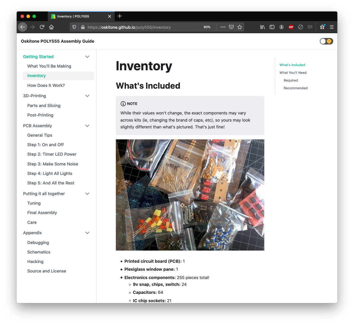
The OKAY kits shipped with their assembly guides printed out and folded into zines, and some even had makeshift-letterpressed covers. There's no doubt a lot of old school charm to that, but it was hard to ensure folks got the best instructions with black ink on dead trees.
So the POLY555's assembly guide is all online, complete with schematics and hacking ideas: https://oskitone.github.io/poly555/
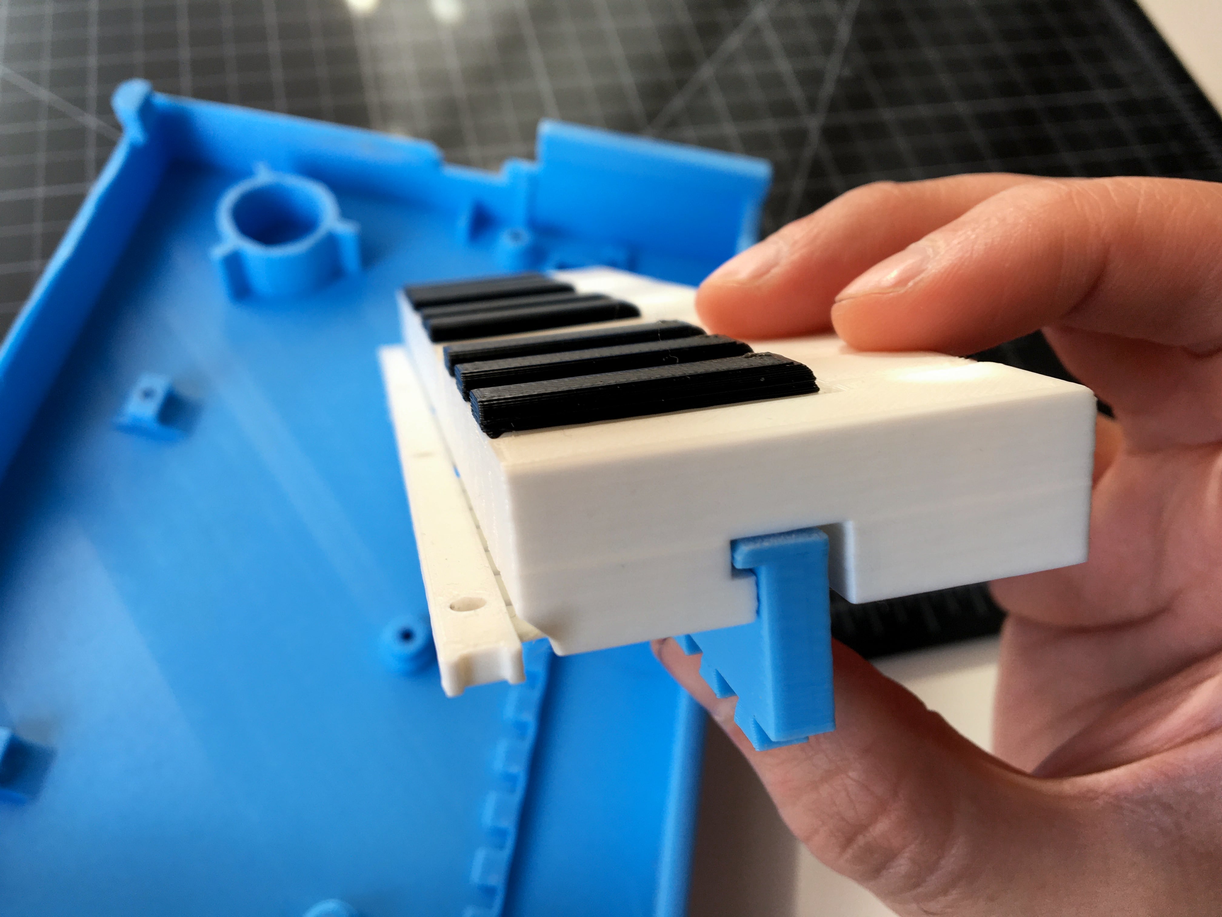
Key endstop
Exhibiting at Maker Faire a couple years ago was like a whirlwind tour of stress testing. If enough force is applied to the keys (Thanks, kids! 😬), they’ll push beyond their buttons and break at the the cantilevers where they mount.
So the POLY555's enclosure has an endstop that fits into a matching cavity on the keys, preventing them from both being pushed too far down and from being pulled up. The endstop cavity on the keys is just tall enough for the travel distance required to actuate the switches before hitting the endstop.
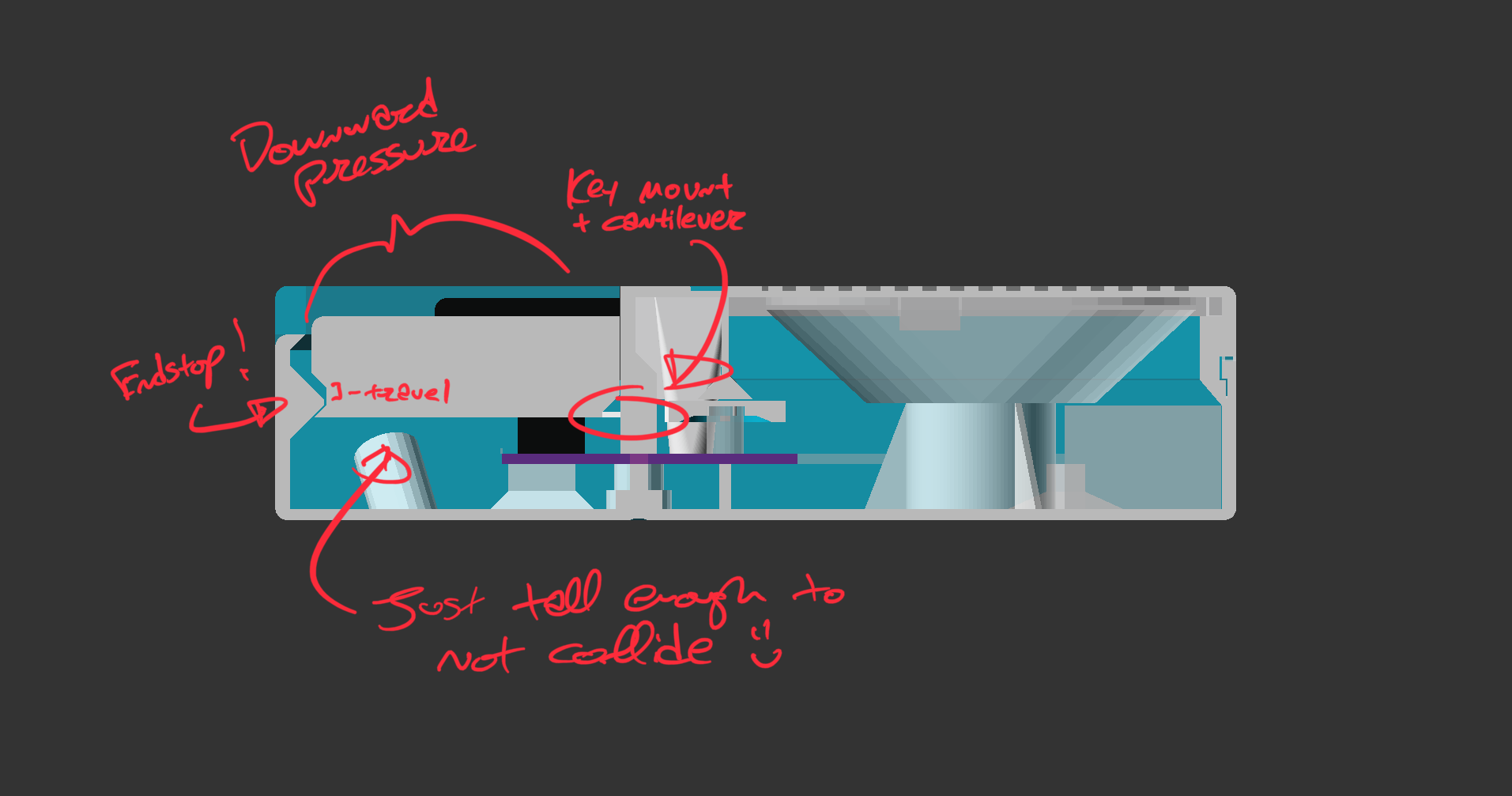
Time will tell if that'll suffice, but it's definitely a step in the right direction.
Prototyping
Prototypes in various stages of scrapping:
^ Dig the cutesy 13 note version!
Abandoned ideas
A recurring theme you'll see in these is that the idea showed promise but just wasn't worth how much effort it required. I'm sure I'll revisit one or two in a future project, where the work-to-reward ratio is better.

|
Course and fine tuners The first PCB used two pots summed together for each timer circuit: one with a 3/4 turn for big, "coarse" changes and another with 20 turns for more precise, "fine" control. In practice, I found I was only using one of them while tuning and the other could just be a fixed resistor. |

|
Speaker on bottom The first prototype tried a wide, flat speaker under the PCB, exposed through the enclosure's bottom. I didn't like that it required the instrument to be raised to prevent muting, nor that the sound was, at best, misdirected. |
|
Keys as speaker grill After the speaker on the bottom, I tried hiding it under the keys and using them as a grill. I do still kind of like this idea, but, like the one above, it requires that the speaker is flat and dinky. I decided if you’re going to spend a long time making something, it should have a bigger sound than what a flat speaker can give, so I moved the speaker out from under the keys and into a sidepanel to the right of the window. |
|
Hinges and clasps The OKAYs used hinges and clasps to make them easy to pop open and display the internals — not nearly as important when there’s a big window built right in. |
|
Lightpipe branding With the speaker in a sidepanel, I tried to showcase the on/off LED indicator with a 3D-printed lightpipe. As much as I would’ve liked to have drawn more attention to the POLY555’s branding, the results weren't worth the effort. |
|
Lit, engraved branding Another idea was to use a super bright LED to light the engraved branding text from underneath. I tried a handful of different LED diffusions, brightnesses, and dispersion angles without satisfaction. Probably needs a lightpipe that 3D-printing alone can't make. |
|
Dovetailed, hitch endstop You can see in some of the pics above that I was trying a key endstop that'd extend up from the enclosure bottom and hitch into both natural and accidental keys. I even briefly had this piece connect to the enclosure with dovetail joints. Abandoned for unnecessary complexity. |

|
Tongue-and-groove enclosure lips The enclosure’s top and bottom were briefly held together by matching tongues and grooves. They were abandoned for not being strong enough. |

|
Handle Ha! |
Get (or make!) your own
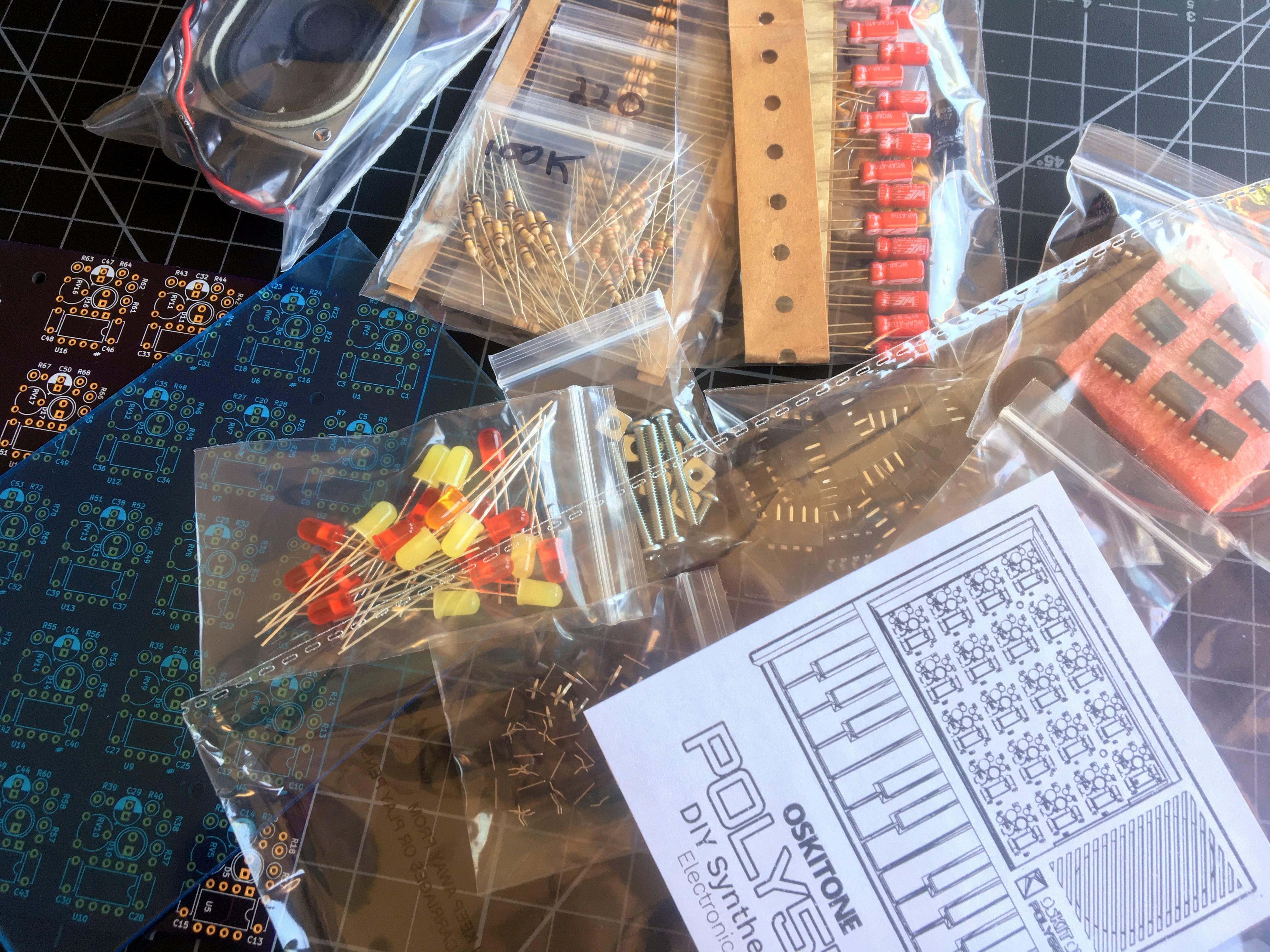
Like the OKAYs, the POLY555 is available for purchase assembled or as a DIY electronics kit:
- Buy the POLY555 Synth
- Buy the POLY555 Synth DIY Kit
For the DIY kits, the 3D models are shared on Thingiverse for folks with ~20 hours and access to a 3D printer.
Open-Source
Unlike the OKAYs, I'm also open-sourcing all the OpenSCAD code used to generate the 3D models, as well as the Kicad PCB project, which I wasn't doing before: https://github.com/oskitone/poly_555
The code is generously licensed. Please reach out to me if you do anything interesting with it or have any questions!
What's next?
Um, probably nothing to do with 555 timers. 😅