Higher Lower
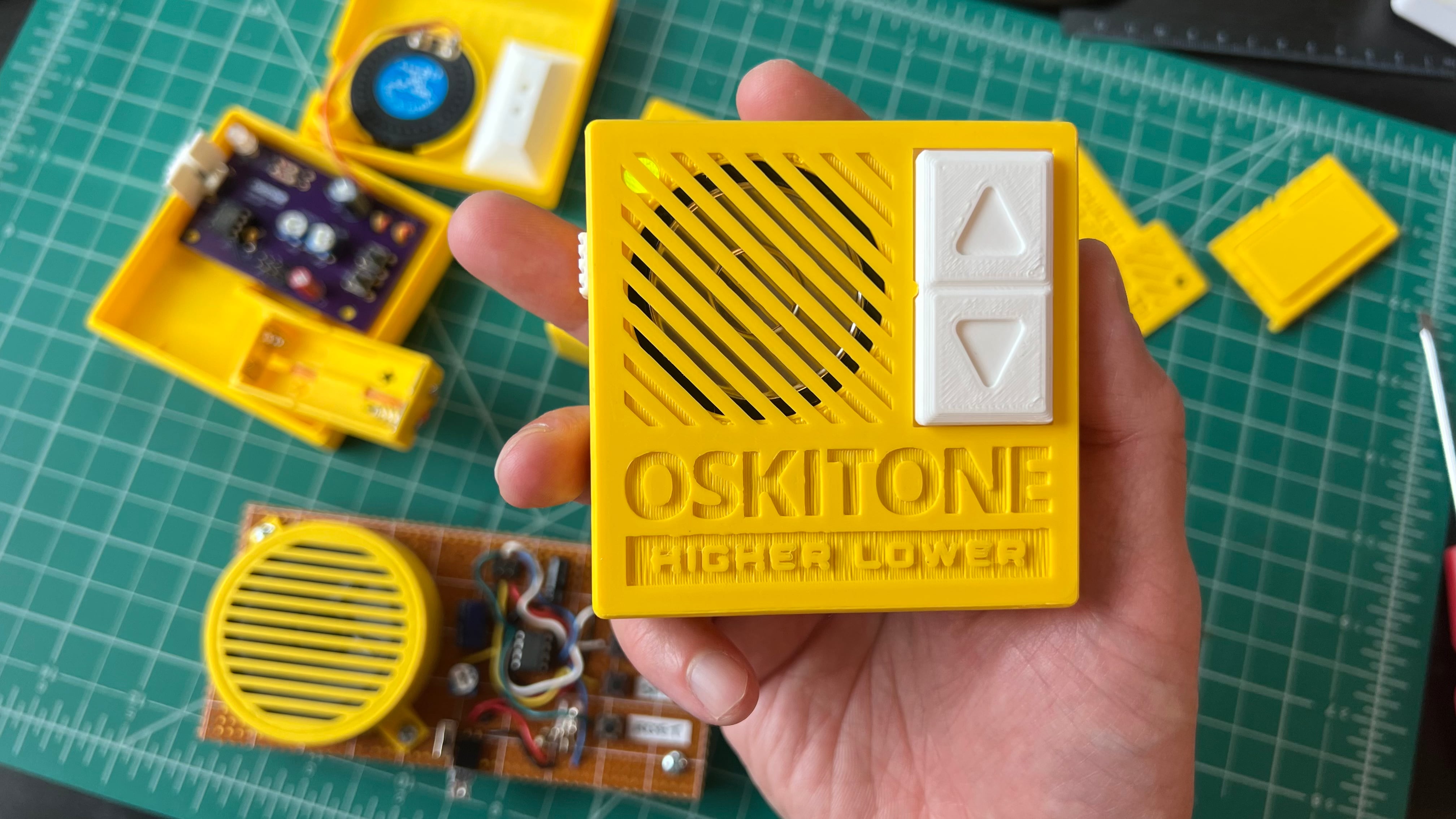
The latest Oskitone kit is an electronic handheld game I made called "Higher Lower," where you have to guess if a tone is higher or lower than the previous one, and the more you get right the harder it gets to tell.
It was fun to make and is fun to play!
Prompt
The impetus for this project was Hackaday's "Tiny Games Challenge":
Sometimes the tightest constraints inspire the highest creativity. The Tiny Games challenge invites you to have the most fun with the most minimal setup. Whether that’s tiny size, tiny parts count, or tiny code, we want you to show us that big fun can come in small packages.
I have a pet peeve about devices too small for human hands, so I interpreted the challenge as a budget on input/output. What's the least a game can do but still be fun? How few controls do we need for input? What can we do without for output?
The microcontroller I targeted is the tiny ATtiny85: an 8-bit and 8-pin DIP chip long popular with hobbyists that I've been meaning to try for awhile now.
(Alas, the contest's deadline came and went without me even noticing, so "Higher Lower" was no contender. Life, huh?)
Design
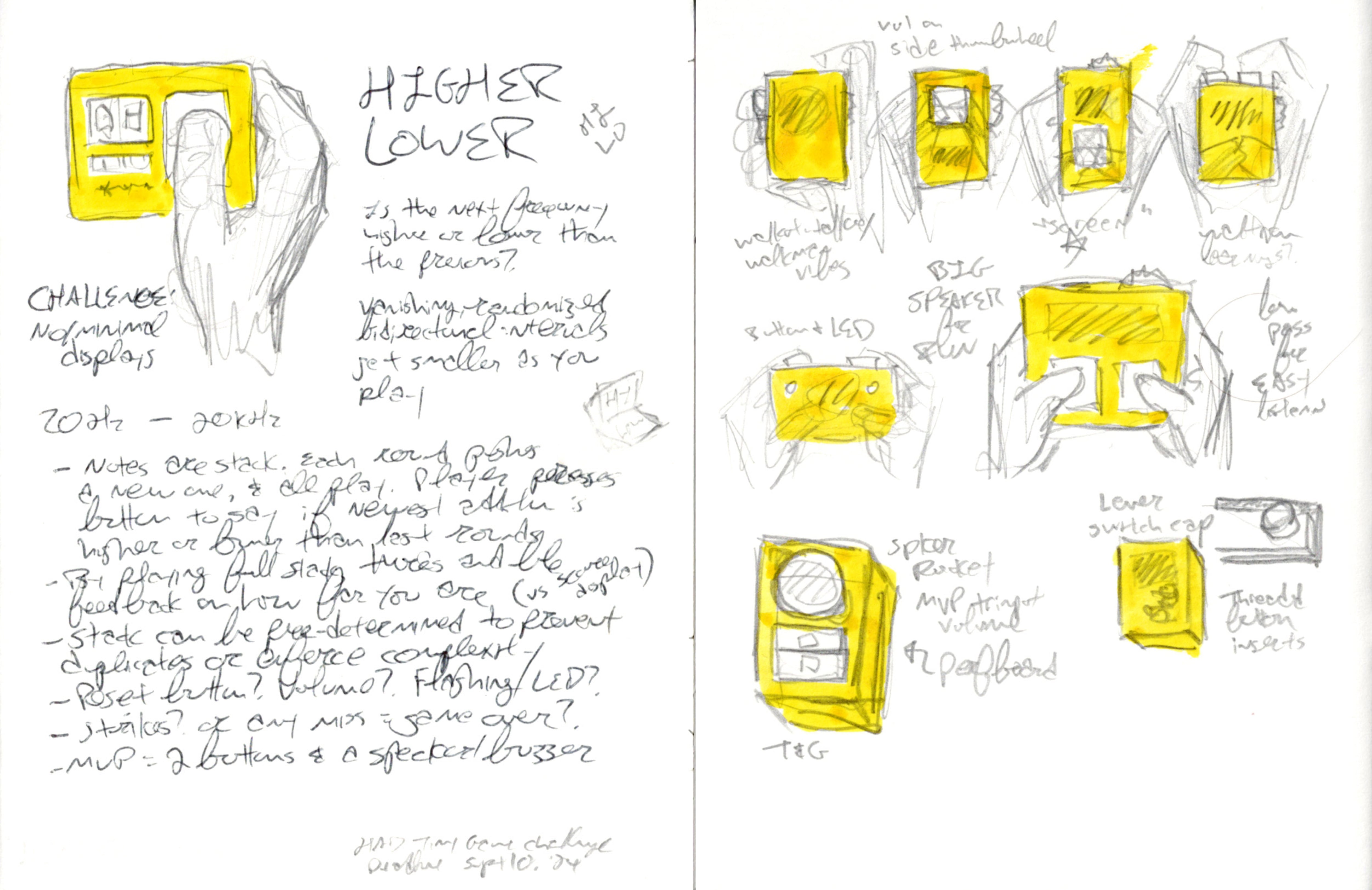
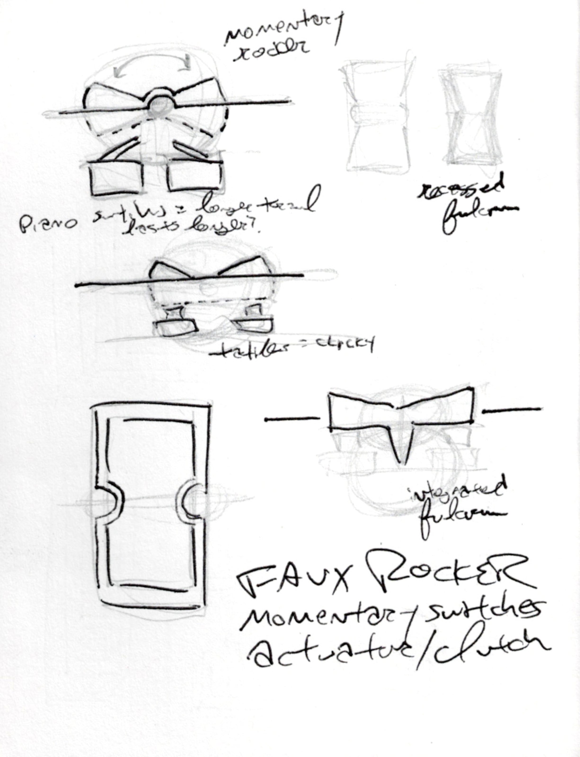
Sketchbook drawings of initial idea and drafts of how it could be held:
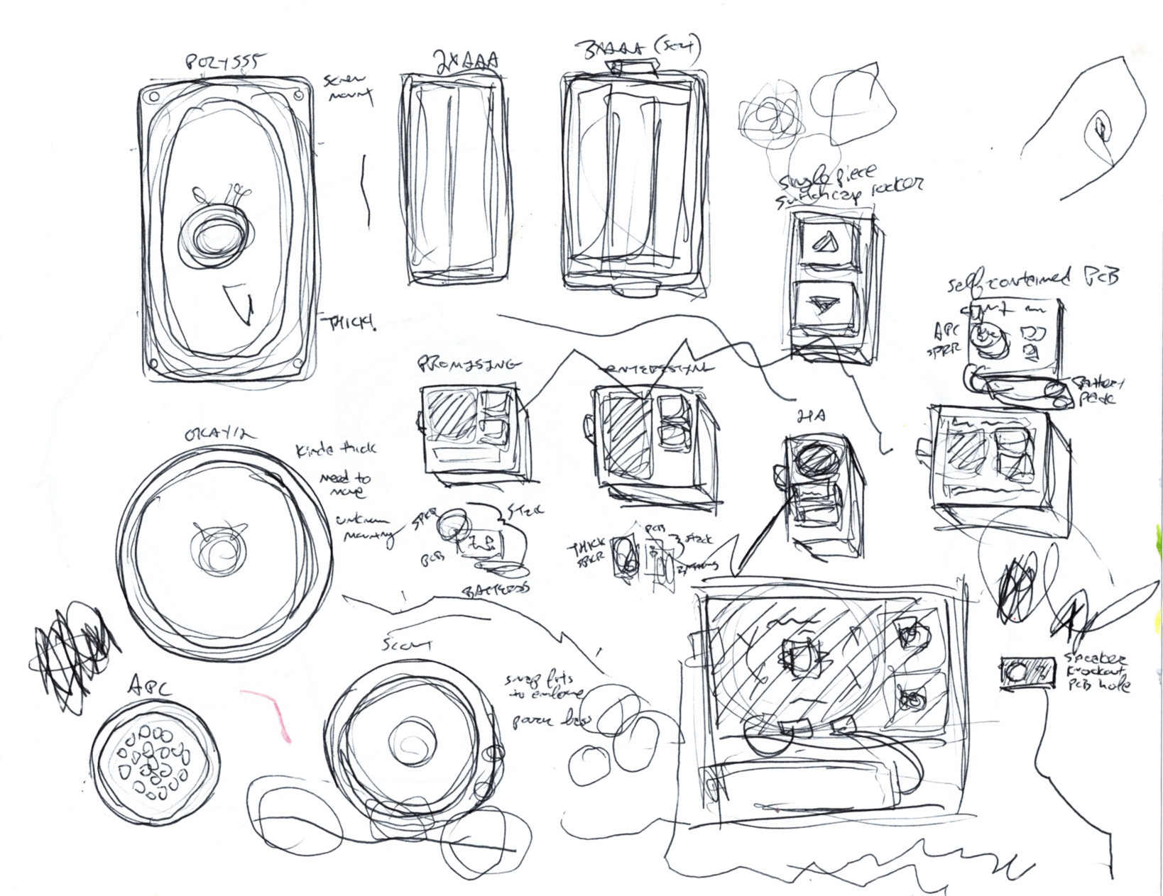
To figure out actual dimensions, I traced some speakers and battery packs. My toddler helped.
Arduboy
The ATtiny85 can be programmed using C++ and Arduino code. Conveniently, so can my favorite DIY game console, the Arduboy.
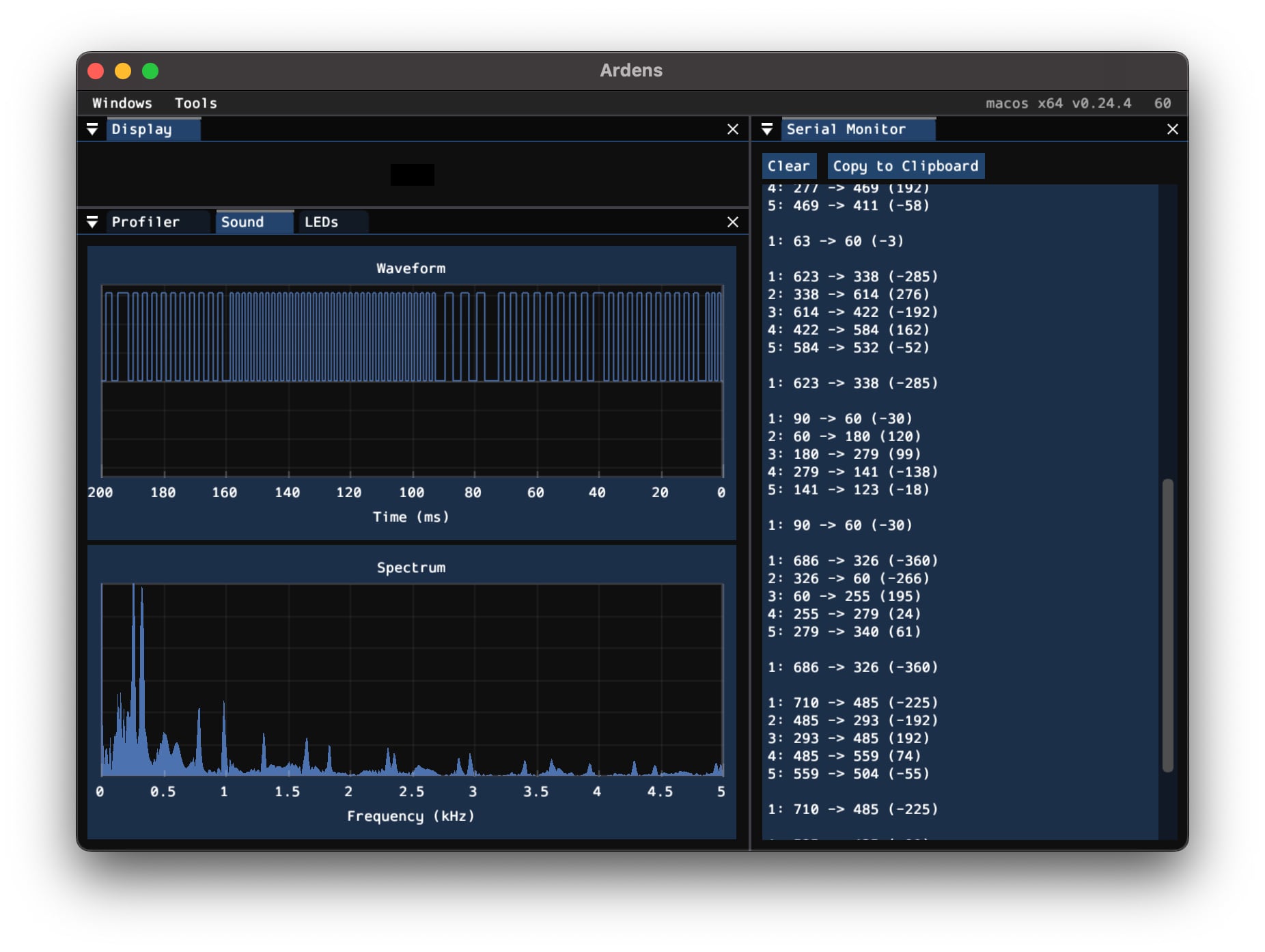
Using the Arduboy for development made for a much tighter feedback loop than programming directly with the chip. And the Ardens emulator means I can work on the game with just my laptop. This is a screenshot of the proof-of-concept, made while waiting at my kid's swim practice:
Notes:
- A regular Arduboy game would have something in the Display panel, but instead I'm using only the Serial Monitor to print out the interval stack; this won't deploy to the final target device. In the Waveform window, you can see the different frequencies of square waves being played.
- The frequency intervals' directions and distances are random, but their distance is waited like the Arduboy 2D6 dice emulator on I made.
- Instead of using a display to present the score to the user, its count rings out audibly after each successful round, like how a grandfather clock gongs the hours to tell the time.
- There are no strikes for wrong guesses or other units beyond points, which I think would be hard to convey easily without a display. Any wrong guess and the game resets to the intro theme.
- After ten rounds/points, the game plays the intro theme in a loop, faster and faster and faster until the device resets. The next game is more difficult, and so on.
- Sound effects are lovingly borrowed from my "Any Kind of Car" game. The theme song is ascending thirds in a C Major scale.
Even though "Higher Lower" isn't an Arduboy game per se, the platform and toolset made a very compelling environment for its development.
Plus, it means I can embed a stylized version of the game right here in this blog post, no special hardware required!:
(Click a couple times to activate, then use up/down keys to play. The default difficulty setting in the emulated game is very easy.)
Hardware prototype
Now to get the game out of the emulator and into the real world...
1. Arduboy to Digispark dev board
The Digispark is an ATtiny85-based development board with a built-in USB plug. I've had a couple counterfeits (unbeknownst to me, I swear!) collecting dust for awhile so it was good to put finally put one to use.
As a perhaps unnecessary exercise in refactoring and space saving, I rewrote any Arduboy-specific code to use standard Arduino functions: swapping ArduboyTones with tone() and rewriting the button handling that Arduboy2 would normally do. The pins were also remapped to the new chip using the Arduboy schematic as reference.
2. Digispark to ATtiny85 IC on a breadboard
The next step was to go from Digispark board to bare ATtiny85 chip. I used Sparkfun's Tiny AVR Programmer and followed their docs.
This step was less intuitive but had some good lessons for me. To get out of the Arduino IDE's menus and codify the settings that worked, I extended the shell script used for development to also handle programmer deployment.
3. Breadboard to soldered prototype on perfboard
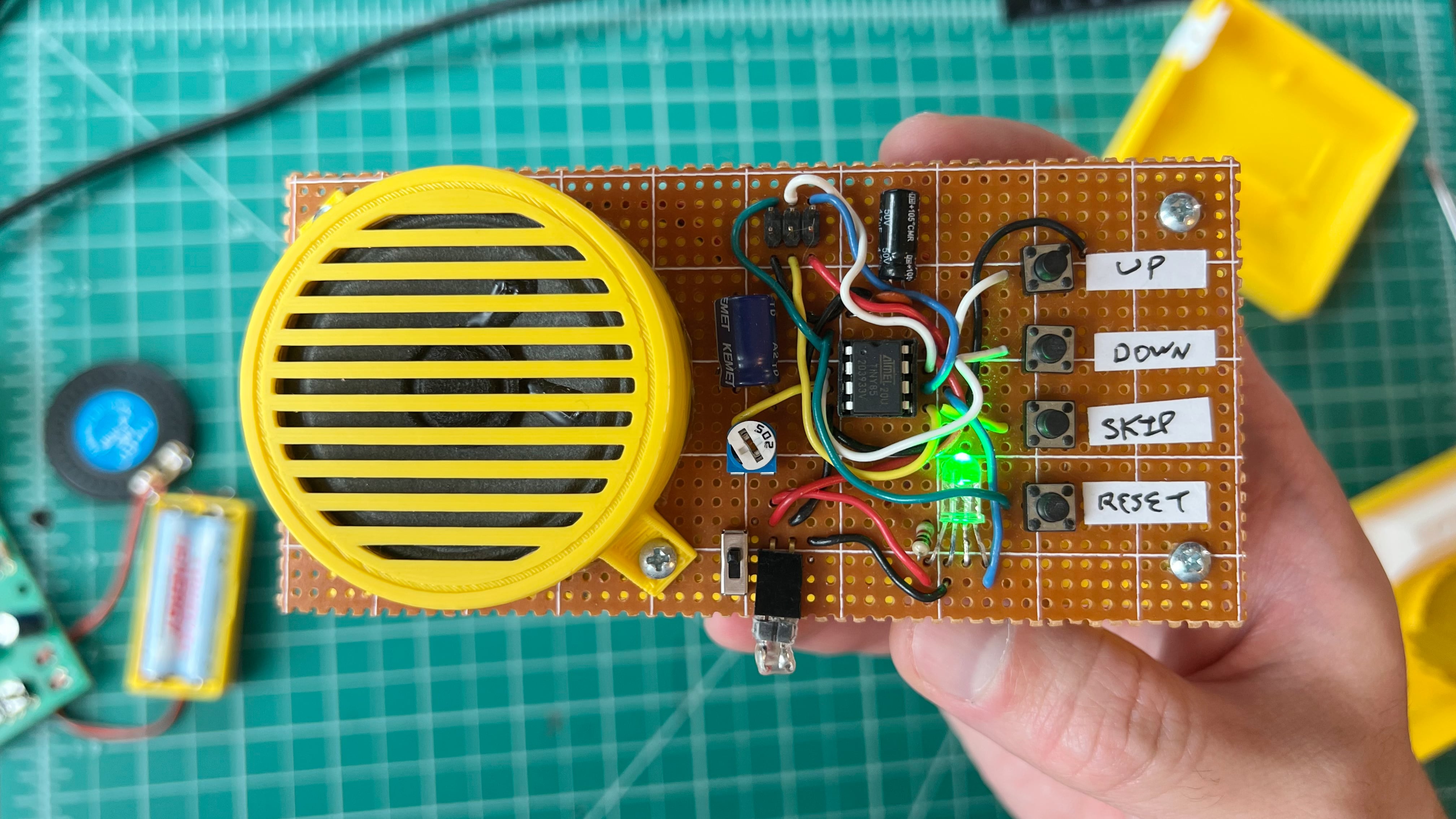
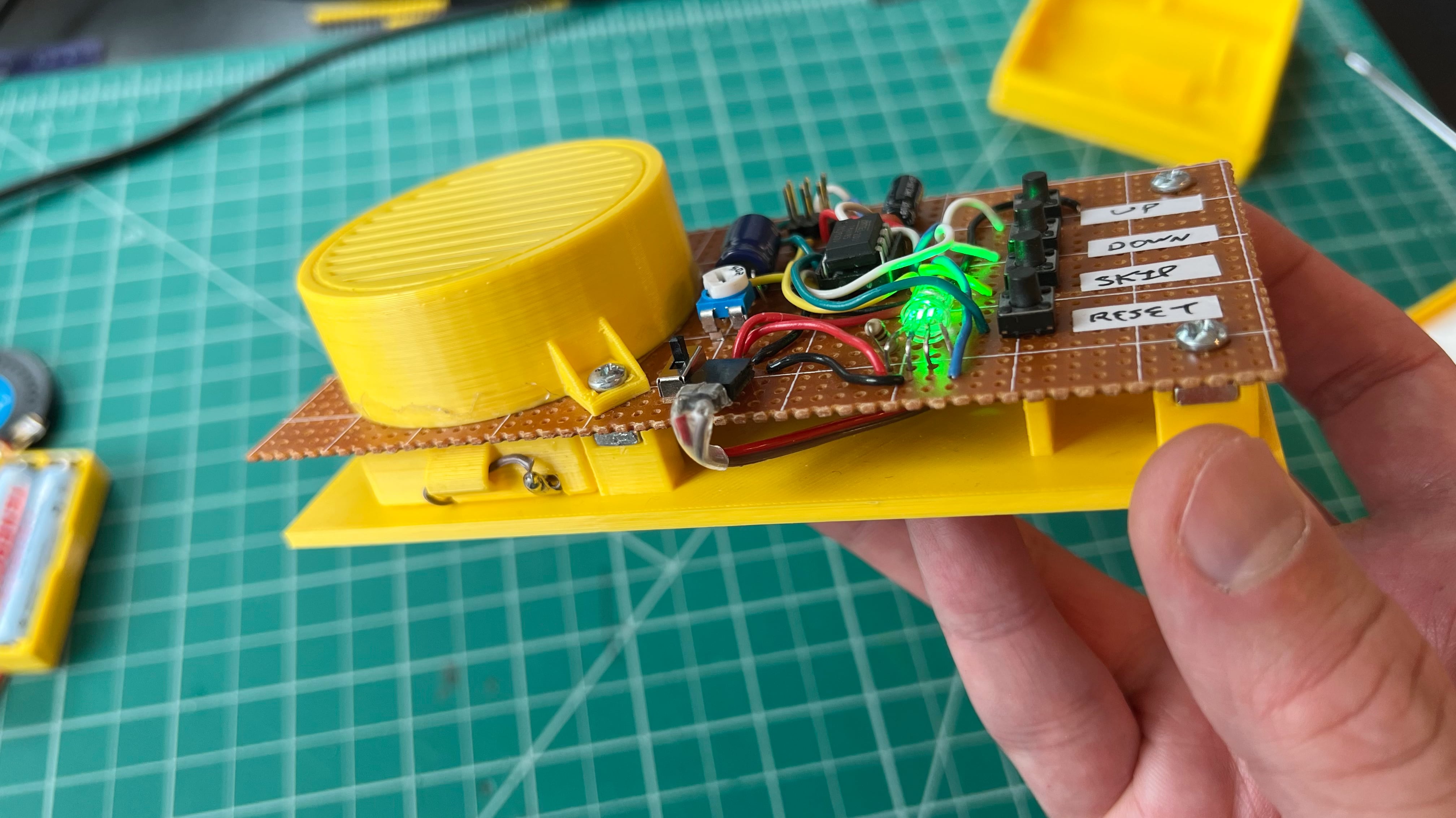
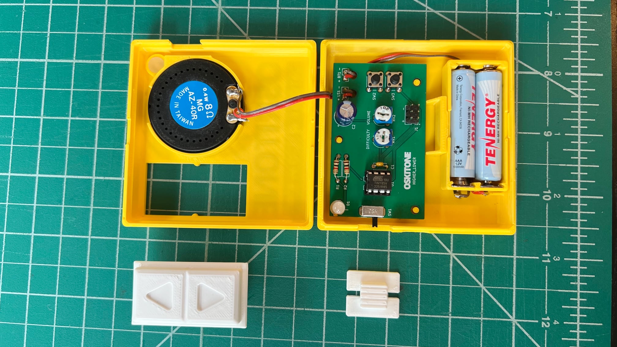
Prototype notes:
- The 2x3 group of pins towards the top is an ICSP header for the AVR programmer to plug into. Alternative options are a UART header like the Scout (requires more parts and program space on the chip) or no header at all (requires swapping the chip to update code).
- The "Skip" and "Reset" buttons are might-as-well for playtesting but don't make it to the final device. Resetting plays the theme song again which my kid likes a lot.
- The schematic for this is roughly the final one below plus the extra buttons and some different cap/resistor values.
- The speaker is a beefy boy left over from the OKAYs. The battery pack is the Scout's 3xAAA battery holder. The speaker fixture and base print are new parts.
I like soldering and prototypes and have opinions on them! (docs from my workshop gig)
Implementation
Schematic
This is the final circuit schematic, made with KiCad:

It's pretty sparse!
PCB
The PCB was also done in KiCad. For a design challenge about making something tiny, it is admittedly not very tiny:
But it makes sense in the context of its enclosure:
Button feel
To test how the rocker will work against its underlying switches, the first PCB rev duplicated them to be soldered at different positions against the rocker. The footprints overlap a little but OSH Park fabricated it just fine, seen here in their "After Dark" colorway:
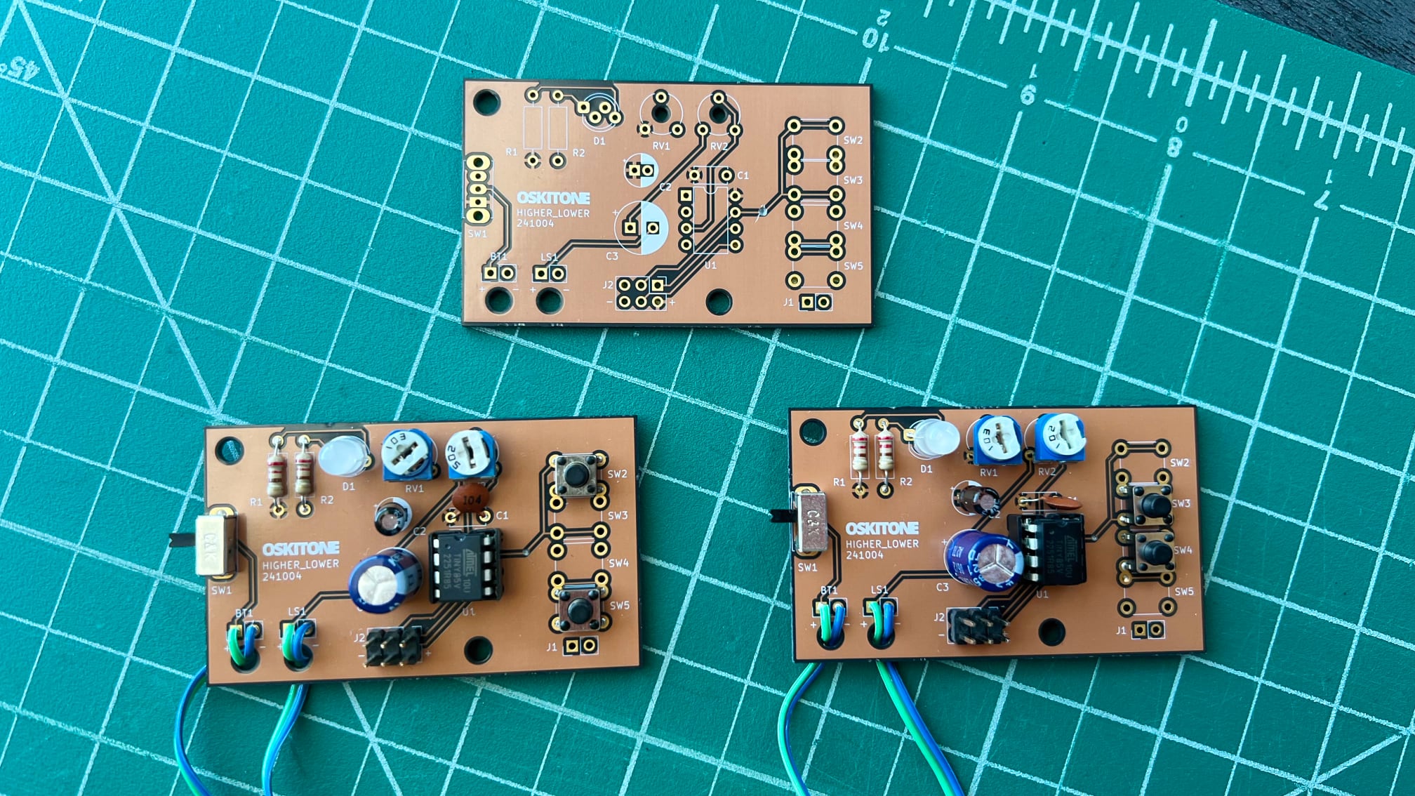
The outer switches, SW2 and SW5, are directly under the rocker pad centers, how a normal "switch cap" would work. The inner switches, SW3 and SW4, are as close to the center as they can be, which is what the final PCB does. In effect, the rocker is a lever.
(The divots in the track from SW3 are part of an unrelated bodge!)
OpenSCAD and final design
All the non-electronics parts are 3D-printed and designed in my favorite programming language for 3D CAD modelling, OpenSCAD. Returning customers will see details from previous work.
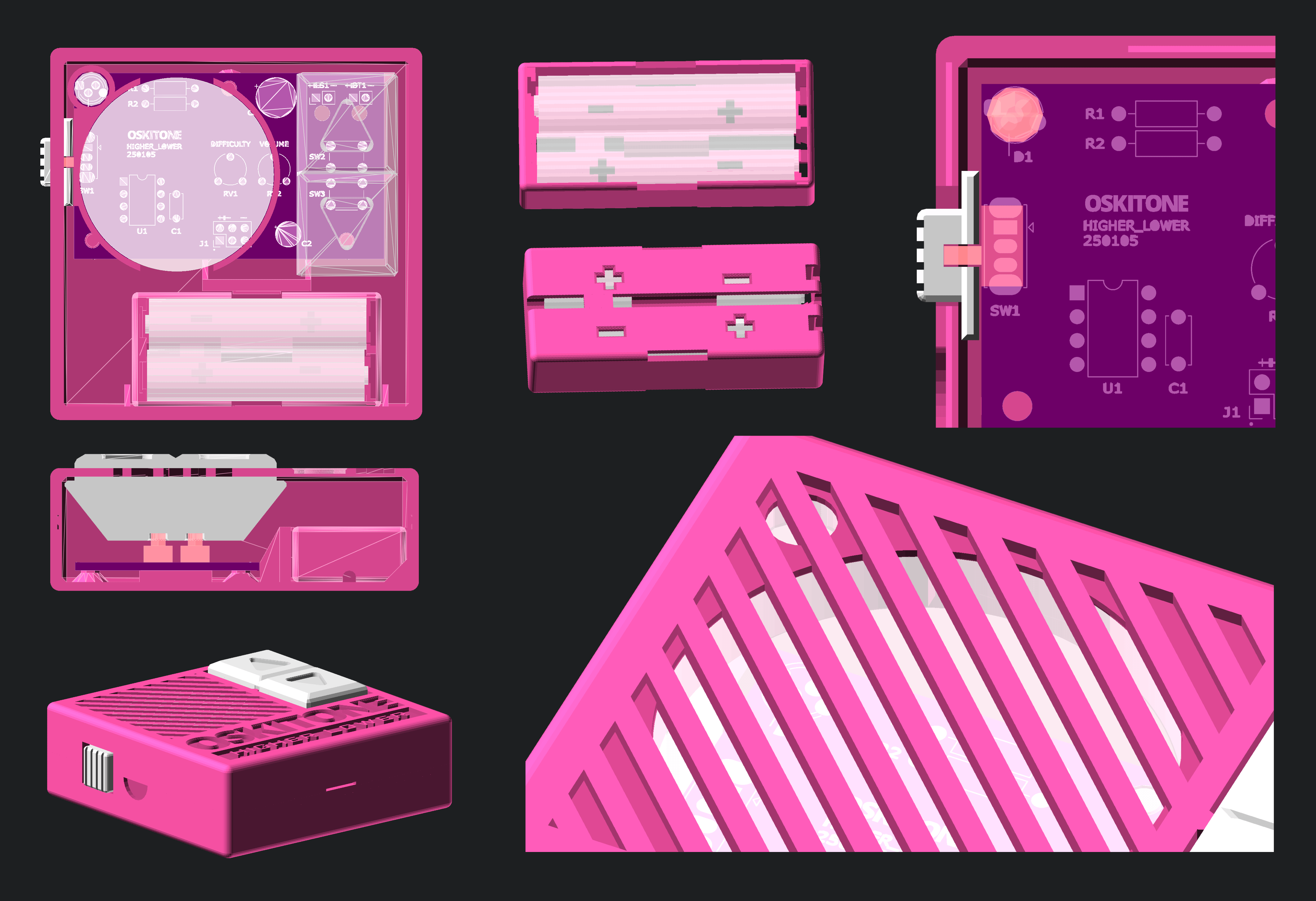
New to the Oskitone design language:
- Button rocker (AKA "D-pad")
Hard to miss this big ol' chonker, huh? This piece sits on top of standard tactile switches, strategically placed for a satisfying mechanical advantage. Cavities on its bottom register the switches' actuators, and nubs on the enclosure top hold it in place during assembly. I wanted to but did not over-engineer it. Maybe later... - Enclosure disassembly cavities
The enclosure snap fit is newly refined for tightness and doesn't need screws. Dimples and wedge cavities along the lip serve as design affordances to (try to!) subtly tell the user how to open it up. - 2xAAA battery holder
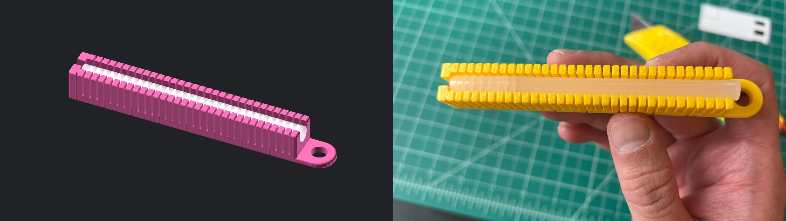
The game is powered by two AAA batteries, housed in a reduced version of the Scout's battery holder. Instead of hitches on the sides to protect against wire fatigue at the solder joint, the wires run through a channel and fixture on the bottom of the holder. - Glue stick lightpipe
My new approach to LED lightpipes is an old maker standard: the humble hot glue stick. An 1/8" segment of standard 1/4" diameter glue stick fits into the enclosure top, discretely exposed in the corner of the speaker grill. The LED isn't necessary for gameplay and I waffled on its inclusion, but in the end I kept it as an assembly guide feedback mechanism — Is the board getting power? Is the chip working? - Hidden settings pots
The game's difficulty and volume are set with trimmer potentiometers on the PCB under the speaker. It's a middle ground between exposed knob controls (too focal) and requiring a code update (too much work). I briefly pursued putting the trim pots on the PCB's bottom and exposing them through the enclosure like the APC, but it wasn't worth the enclosure height increase.
Available... now!
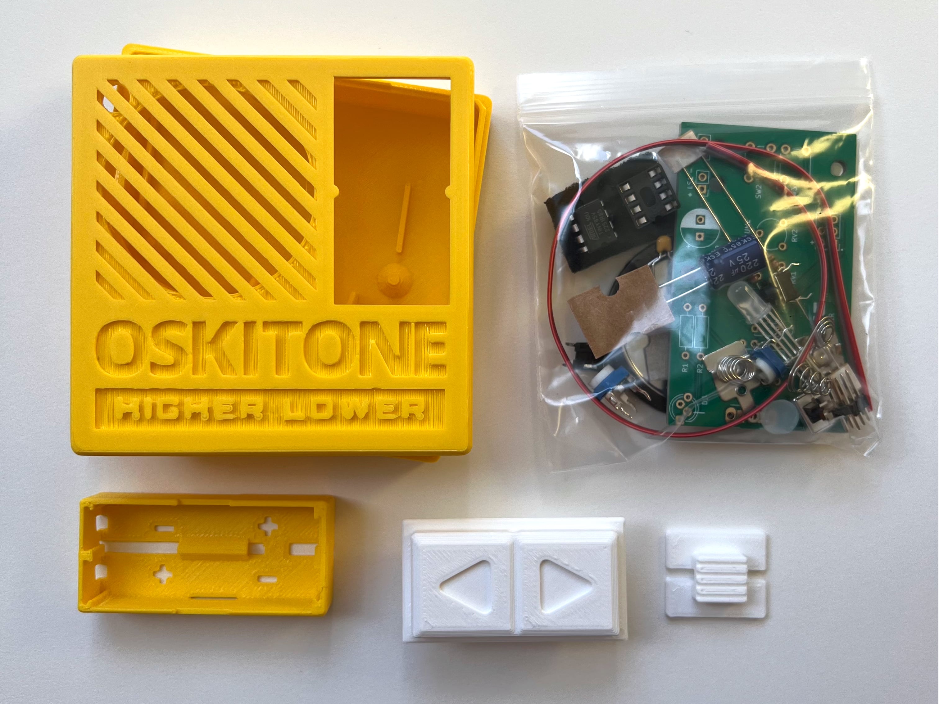
You can purchase the Higher Lower Game DIY Electronics Kit from the Oskitone website. It takes about thirty minutes to put together, a little more if you're new to soldering. It is reasonably priced.
Have a 3D printer? The part files are available to download from Printables and Thingiverse.
Not everyone will want a full kit and there're many places in the world I can't sell well to, so I've additionally made the final Higher Lower game PCB available on OSH Park. I don't make any money from this but I'd rather the business go to them than anywhere else!
Documentation
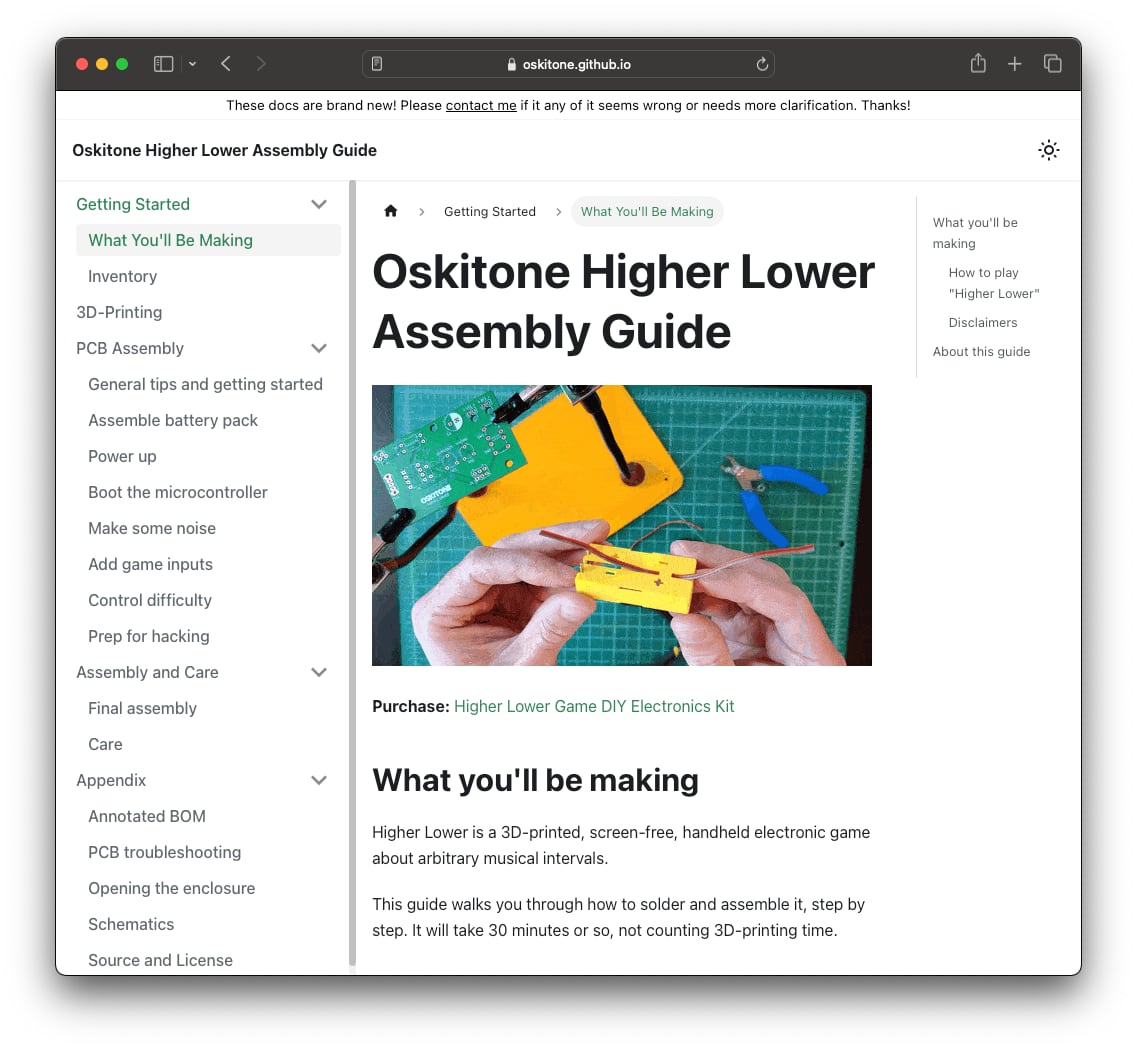
Oskitone Higher Lower Assembly Guide: https://oskitone.github.io/higher_lower/
Like the other Oskitone guides, soldering is ordered by function (not by component type or size, which is typical) with clear tests at the end of each step so you know if it's working as expected before moving on.
New to the docs are "How it works" sections on each step too. What are these components doing? How is the microcontroller using these switches and pots? Wait, what even is a microcontroller? Some questions are hard to answer conclusively without writing a whole book, but an attempt was made!
Source
Source code and design files are open-source on GitHub, per usual: https://github.com/oskitone/higher_lower
Appendices
Two batteries, not three
The operating voltage range of a standard ATtiny85 is 2.7v to 5.5v.
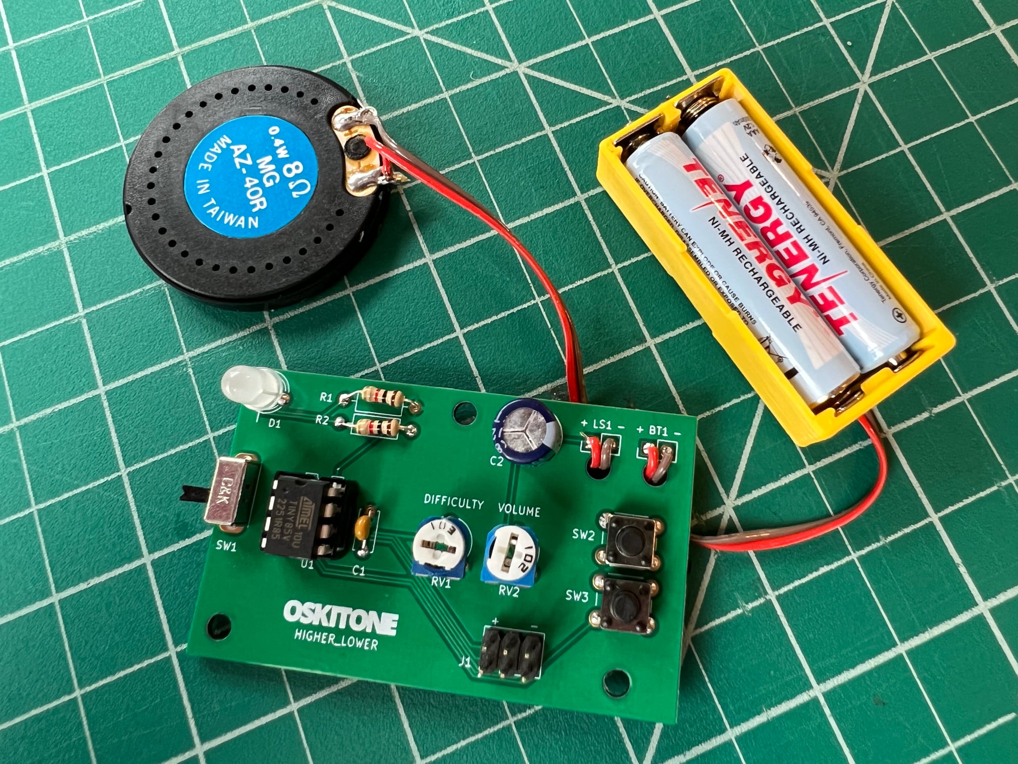
A rechargeable NiMH AAA supplies 1.2v, and three of them make 3.6v, which is perfect! That's what the Scout does, and it's the Scout's battery holder pack powering the game prototype above.
The problem is that 3 AAAs plus the PCB length made the enclosure dimensions a kind of awkward rectangle, when I wanted it to be a square.
Dropping to two NiMH batteries for a total 2.4v isn't enough voltage, and I dare not prescribe non-rechargeable alkaline batteries even though their nominal 1.5v (thus, 3v total for two) would work great.
The solution was to switch to the ATtiny85V, a special version of the chip that runs on lower voltages, as low as 1.8v.
So RANDOM
Random number generators need a seed number to start, otherwise they'll present the same sequence repeatedly.
An unconnected chip pin has a value that's either high or low (or, in binary, 1 or 0), which is theoretically an okay seed. But, in practice, I didn't have much luck with this technique.
Now a great seed would be the number of milliseconds it takes for the user to take an action, which is not only higher than 0 and 1 but also almost certainly unique on each play. (This, btw, is how a lot of those "Prove you're not a bot" captchas work. They're not checking your answer but rather how long it took you.)
But if the game starts immediately on boot and launches right into the first round of should-be-random intervals, when can we get something like that?
The compromise I made was to delay randomization until the user has finished the first round, guaranteeing a unique millisecond seed each time. The first round's sequences of notes are fixed and from the intro theme, so it also feels like a nice, musical ramp into gameplay before the intervals become arbitrary.
Lightpipe cutting jig
To make the lightpipes, I first made this cutting jig. It holds the hot glue stick in place with slots at 1/8" intervals to run a utility blade through. The hole on the right is a "checker" that matches the lightpipes dimensions.
Parts Café
Since so many projects are sharing so much OpenSCAD code, I've started to extract as much as I can into a common Oskitone parts library, parts_cafe:
- The prototype's base and speaker enclosure seen above
- A "print test" for 3D printer calibration
- Lightpipe cutting jig
- Almost everything else you've seen in my projects: enclosures, engravings, piano keys, PCB mounts, fixtures, etc
There are better options for OpenSCAD parts libraries so I don't recommend anybody really use it (and I have no immediate plans to add any real documentation or offer support), but it's here for the curious: https://github.com/oskitone/parts_cafe
multi_tiny
The Sparkfun AVR programmer I'm using is designed to program one chip at a time, and it works great for that!
But if you want many chips programmed, your options are basically 1) a bigger programmer or 2) to outsource the programming.
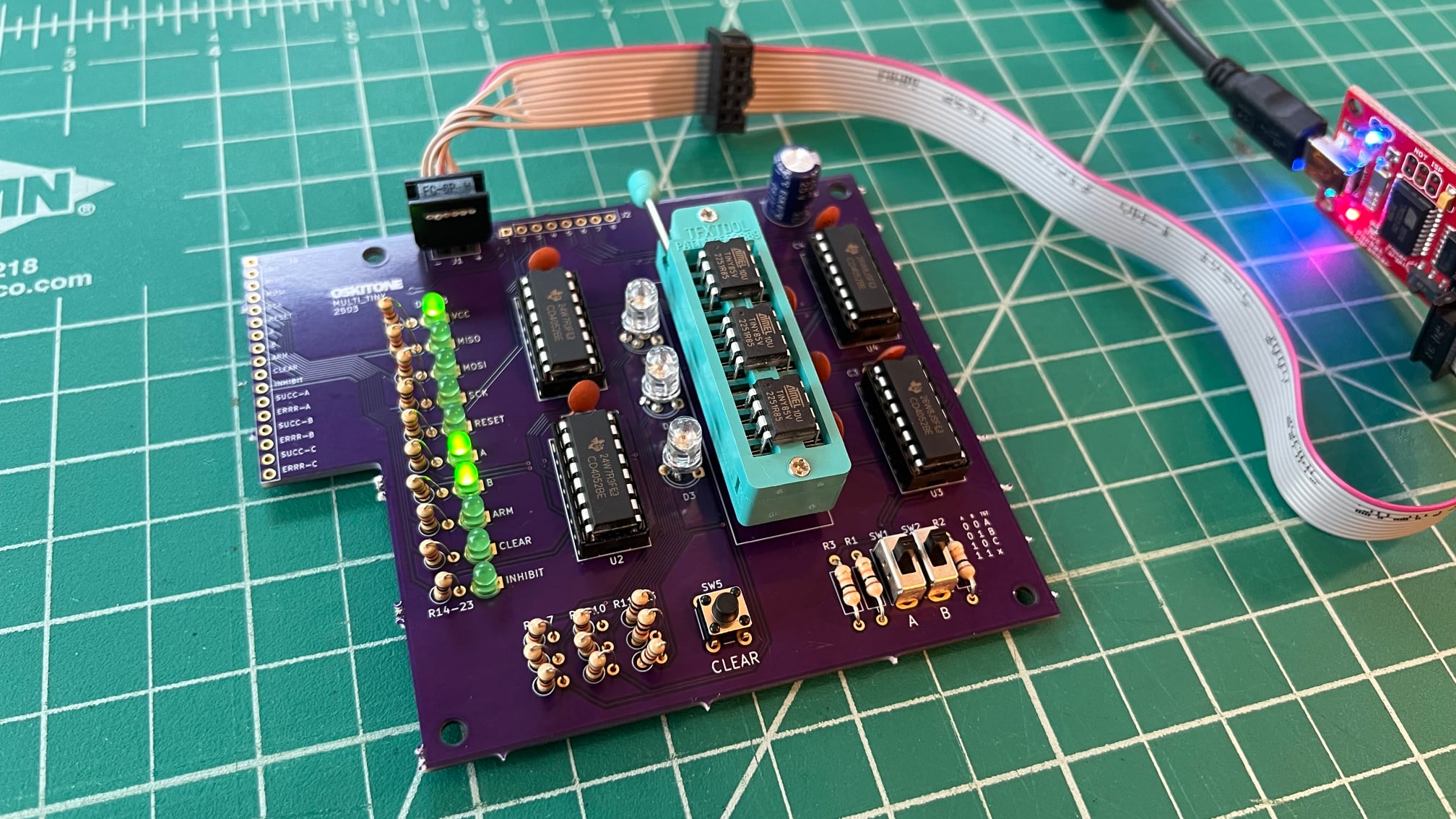
This multi_tiny PCB is my research side-quest into how to connect multiple ATtiny85 chips to a single programmer. The idea is that the programmer's pins go through multiplex switches that direct them to different target chips' pins. When they're done programming, they pop out easily from the ZIF (Zero Insertion Force) socket. The multiplex destinations can be set manually, but the end goal is to control them digitally with another device that also handles queuing, testing, statuses, chaining...
It's a promising start but very much a work-in-progress. Follow along here: https://github.com/oskitone/multi_tiny
An animated GIF of the OpenSCAD development, git commit by git commit
As one does.