buttonpusher: a Machine that Pushes Buttons
I made a machine to automate some of the boring parts of Animal Crossing, and it is very satisfying to me.
Like my other projects, "buttonpusher" was designed in OpenSCAD and 3D-printed. The code controlling it is CircuitPython, running on an Adafruit Metro M0 Express.
Code, circuit, and 3D models to make your own: https://github.com/rocktronica/buttonpusher
How it works, briefly
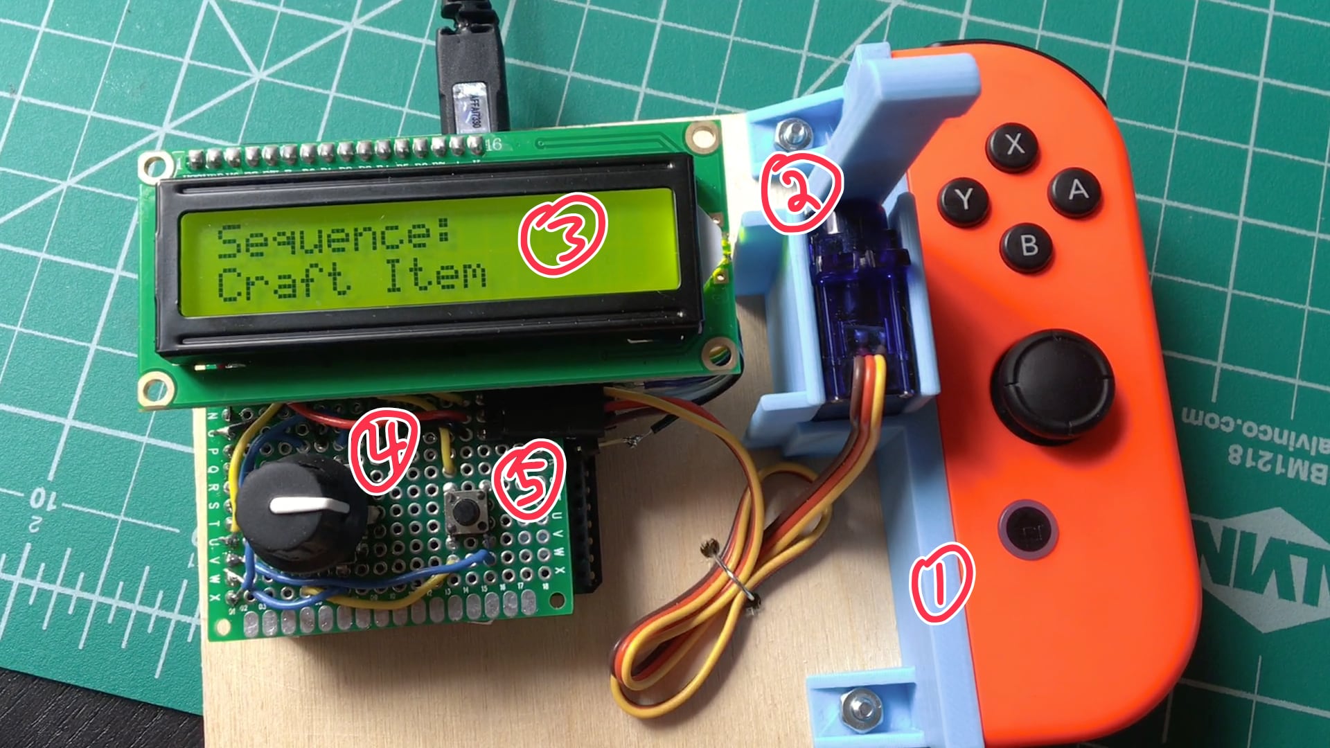
- The Nintendo Switch's Joy-Con slides into a matching rail.
- A servo rotates a hammer arm that swings over to press the "A" button.
- Menu and progress are displayed on a 16x2 character LCD.
- A rotary encoder allows for sequence and count menu selection.
- A small tactile switch lets the user halt any running sequence or navigate back in the menu.
The sequences on it are hardcoded for Animal Crossing, but it could be easily extended for other games or usages, as long as the only button required to push is "A" and the timings are fixed.
Lessons abound
Yes, this is "Yet Another Unnecessary Thing," but it was a good excuse to get familiar with some unfamiliar tech like rotary encoders and LCD character displays. Per usual, I got some nice takeaways too.
Lesson 1: Don't lose force
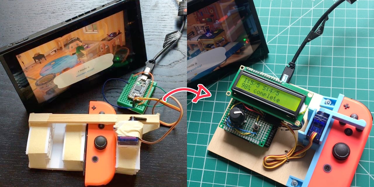
The first version was made out of foamcore board, masking tape, and craft wood. It didn't have a menu or display and needed to have its code updated to switch the sequence or count. Still, it worked pretty well!
It used a wooden lever to push the button, and I think that made me think the servo was underpowered and not strong enough to push the button all the way down.
But I was wrong! The servo was indeed strong enough -- it was just losing torque through various design flaws that were fixed in the eventual 3D-printed version:
- The Joy-Con controller mount is extra tight fit so there's no room to wiggle
- A stool under the Joy-Con provides an opposing force when the hammer fully descends
- And walls on opposite side of the servo prevent it from rocking back and away from the Joy-Con
- The hammer arm first connects to a stock servo horn before its axle -- this avoids fine wear-and-tear and eventual slipping from the 3D-printed plastic
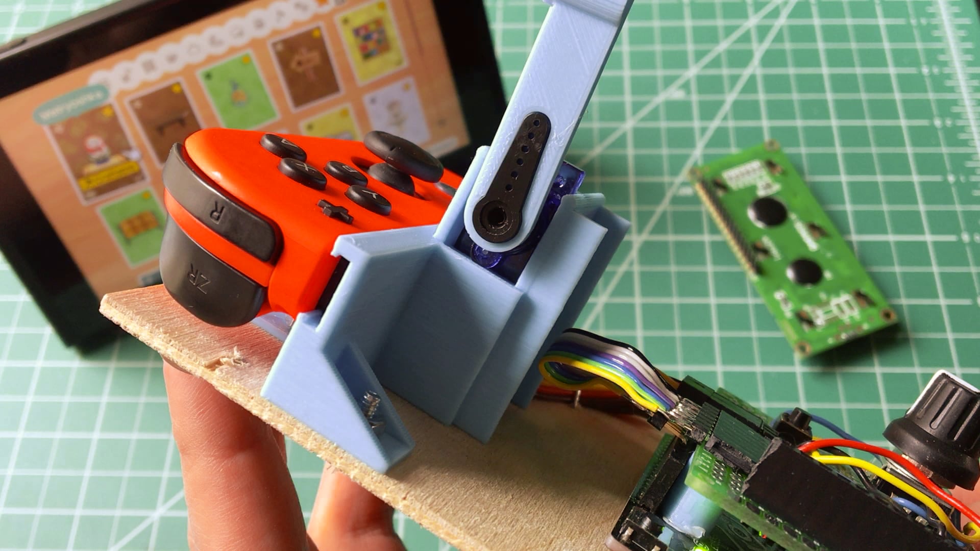
We basically want to keep the connections between the servo, its horn/arm, and the Joy-Con as fixed and rigid as possible. Any looseness is a loss of force that would otherwise be used to push the button.
Lesson 2: Use what ya got
Speaking of that hammer arm...
I'd intended for the arm to attach directly to the servo axle (and even spent a good amount of time dialing in the exact fit for its cavity) but it ultimately didn't work because the "teeth" on my 3D-printed part quickly wore out and lost their grip on the axle.
Instead, I modeled one of the injection-molded propeller horns that came with the servo and used it as the cavity for the arm. With cheap plastic, bigger is better.
Alternative 1: Screw the arm horn tight into the servo, but I was worried about stripping it out while iterating on the design
Alternative 2: Upgrade the plastic, which I just wasn't jazzed about
Lesson 3: Save your memory
With all that CircuitPython code, I found myself quickly running out of memory on the Metro M0 Express and needed to compile all the .py Python files into .mpy MicroPython bytecode files that consume less memory when deployed.
To make that easier, I wrote circuitpython_tools, a work-in-progress shell script that watches for local changes then automatically compiles and deploys to the board, saving me LOTS of time.
(The novelty of automating things while making a thing that automates things was not lost on me!)
Lesson 4: Consider footprint when choosing a microcontroller board
When I added menu controls and the LCD display, I had to upgrade the board to something with more IO pins.
And the only board I had around and fit the bill was a Metro M0 Express. It has a pin layout like the Arduino Uno: two rows of pin headers and (I learned the hard way) irregularly spaced pins on one side that don't match standard .1" perfboard spacing.
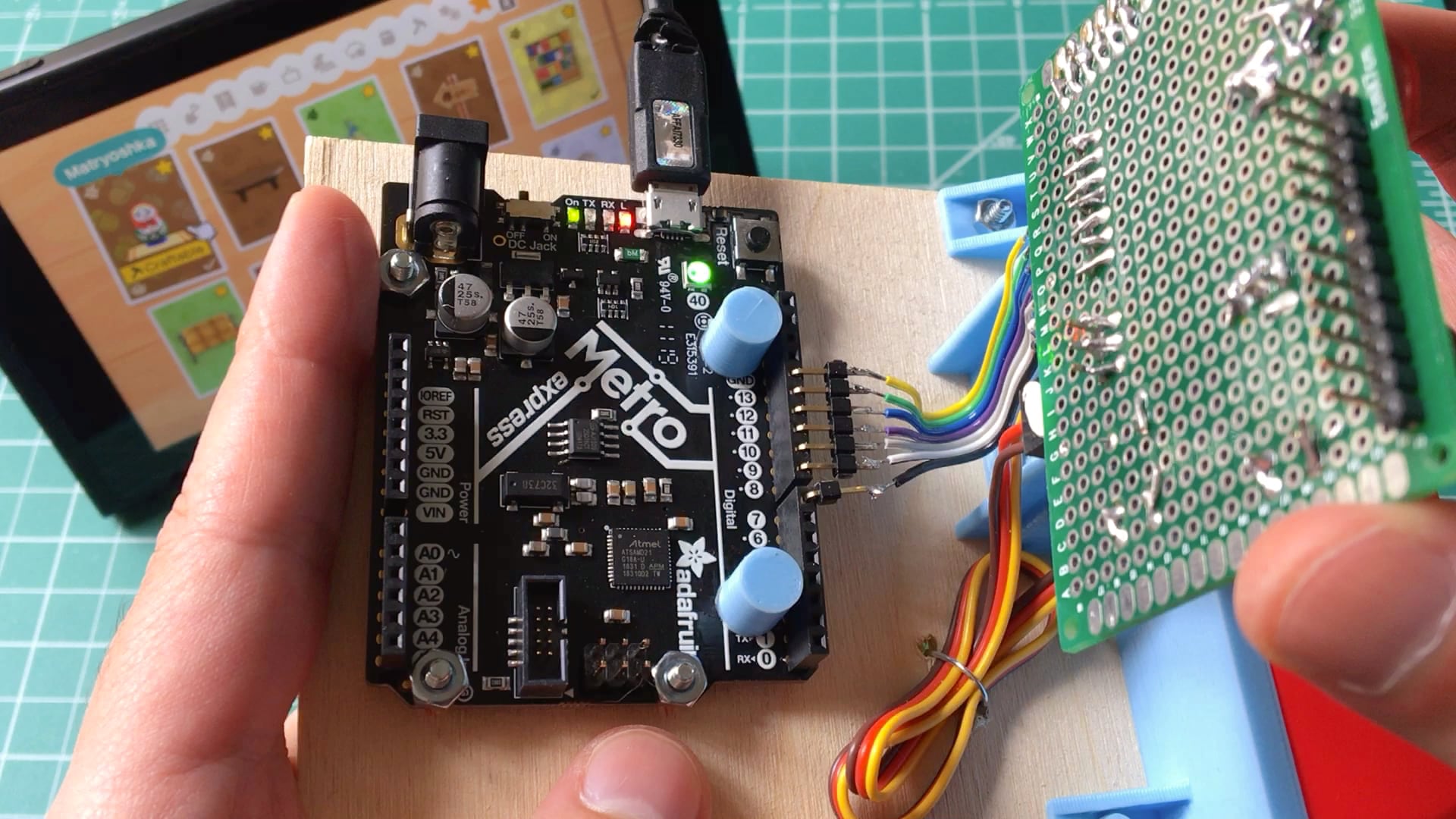
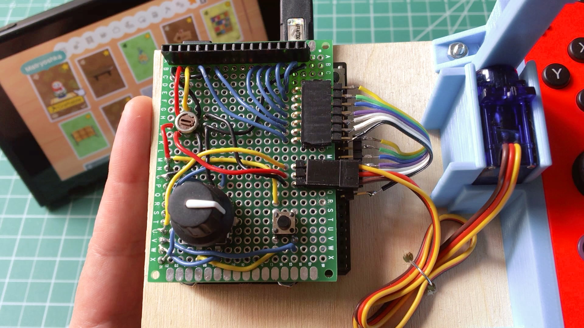
The electronic components connect to that board by a one-off PCB (a "shield" in Arduino parlance) that I hand-soldered. Because I 1) wanted to solder to both sides of the shield, 2) didn't have a double-sided perfboard big enough, and 3) had to work around the Arduino's unfortunate pin spacing, my shield uses right-angle headers and ribbon cable to connect to the character LCD. It's then supported by crude 3D-printed standoffs where the headers should have been.
Here's the shield stacked on top, without the character LCD:
For future projects like this, I'll save some headaches and go for a smaller board with a standard pin spacing. Good lesson.
Et cetera
Other stuff I'm proud of
- The math to calculate percent completed and timing is, I think!, pretty cool. It tries to honor the prescribed sequence timing by automatically making up for variances in servo/LCD update times, while updating the display in realtime.
- Design For Manufacturing, or ways the models avoid supports when printing:
- The cavity in the Joy-Con mount has super small columns distributed across its length. These easily break away when assembling.
- The hammer head has a flat side so it can print laying down without supports.
- The servo clicks into a cavity of its negative and doesn't need screws. Not that I'm opposed to that, it just wasn't necessary...
- The Python code is blackened.
Open questions
- Are there uses for this outside of novelty hacking? Assistive technology?
- How could it work with different controllers or game systems?
- Can it push more buttons?
- The servo could probably be replaced with a solenoid and lever. (Not a question, I guess.)
- What would an enclosure look like? Could the arm retract into it somehow? How about a battery pack to work without the USB cable?
- What if it had Joy-Con mounts on both sides? Or if it mounted in between the Switch's screen and controller?
Appendices
Appendix A: Visualizing progress
While procrastinating on writing this blog post, I hacked out some quick scripts to visualize the design's evolution from its git commits. You can see the Joy-Con mount getting fine-tuned, iterations on how the servo attaches and is supported, its horns and arms, its abandoned lever idea when I thought the servo was too weak, and tweaks on the final screw mounts.
Appendix B: Is this a hack?
While showing this project to friends, an interesting topic came up: Is this hacking?
I'd argue that it's not. There're no modifications to the original Nintendo hardware nor its software. The machine is physically doing a job no different from my thumb, and it's not even smart about it: the sequence timings are programmed beforehand, and it has no feedback loop to know if they're completed successfully.
But it's easy to imagine versions of this "machine that pushes buttons" idea that creep closer to something Nintendo would disapprove of, where, in each step, the human interaction is abstracted futher away from its consequences:
- What if the button pushes weren't mechanical? The button's pins could be soldered to relays or maybe a 4066 chip, allowing its circuit to be closed electronically without any physical movement.
- Another version skips soldering entirely and has the code directly interface with the console to emulate button presses.
- The Switch's video output could be analyzed in realtime, and OCR could be used to read the dialog text. Instead of it being programmed beforehand with the sequence's timings, it could adapt automatically just like a human would.
- Soon enough, the game has an API and a bot could be trained to play it.
(Beyond #1, I have no idea how to do any of that.)
If those ideas are laid out in a spectrum with buttonpusher at the front, it seems to me that the definition of hacking is an arbitrary line that we all draw somewhere. "This is okay and this is not."
Just some thoughts!