Prototype Post-Mortem: Four-Step Octaved Sequencer
Four-Step Octaved Sequencer from oskitone on Vimeo
Background
The first version of this sequencer idea was a collaboration with an artist named Rasterstache. It displayed at Maker Faire and eventually made its way to the popular Chicago band OK Go:
— OK Go (@okgo) November 4, 2017
A look inside
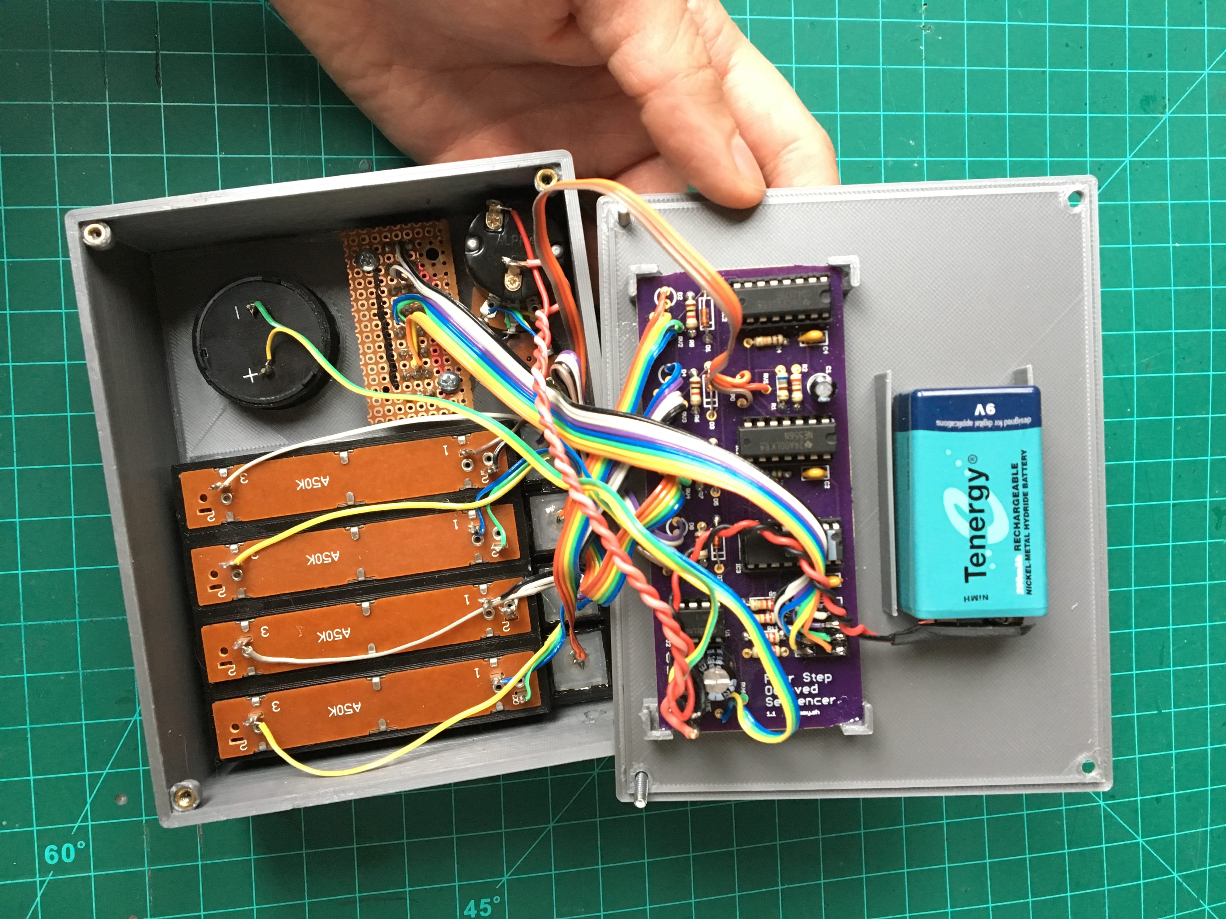
Inside that robot figure is a really pretty, one-off, hand-wired circuit I made on perfboard.
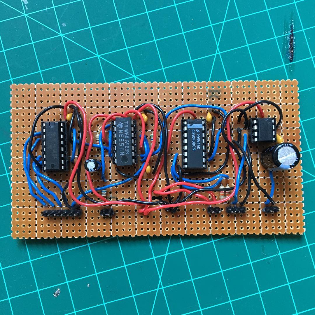
(IIRC, blue wires are IO (in/out) between chips, red/black are power/ground, and all IO to/from the board connected with those black headers. I was apparently big into headers at the time; I think I'd do that differently if I did it now.)
Here's its description that I sent to the artist:
I'm calling it a "4-Step Octaved Sequencer", and it's some kind of musical instrument or noise art machine or even a crude analog synthesizer. There are similar instruments, but I haven't seen one exactly like it -- It is definitely an original, one-off piece of DIY engineering.
In music, a sequencer is a piece of equipment that repeats through a series of notes to make a melodic, looping riff. You're hearing sequencers all the time if you listen to electronic music. Anyway, this one has four steps.
It's "octaved" because its output is actually two square waves mixed together; the main frequency is divided to make an octave lower, and the two are added together for a thicker, richer sound.
An extra neat thing is that, like the rest of my work, this is a fully analog (ie, NOT digital) machine. There are no computers, microcontrollers, sound samplers, or any technology basically from after the 1970s involved. The sound you hear is the sound of a speaker being abused by electricity which has been manipulated by discrete electronic components like capacitors and resistors and logic chips. It is super old school (and unnecessarily complicated) stuff.
For the curious, the IC chips are:
- a 4017 counter to count and iterate through each sequencer step
- a 556, which has two 555 timers to 1) set the tempo for the 4017 and 2) make the main (high) pitch
- a 4040 divider to make the aforementioned octave below the main pitch
- and a 386 amplifier to take the summed octaves' output and drive the speaker
The two octaves I mentioned are easier to see on an oscilloscope. This was the breadboard proof-of-concept before soldering:
Four-Step Octaved Sequencer breadboard from oskitone on Vimeo
Besides the 4017 counter to count through the steps, the circuit is identical to the OKAY Synth's: potentiometer(s) set frequency on a 555 timer, which is divided by a 4040 to make octaves, and then sent to a 386 amp.
From perfboard to PCB
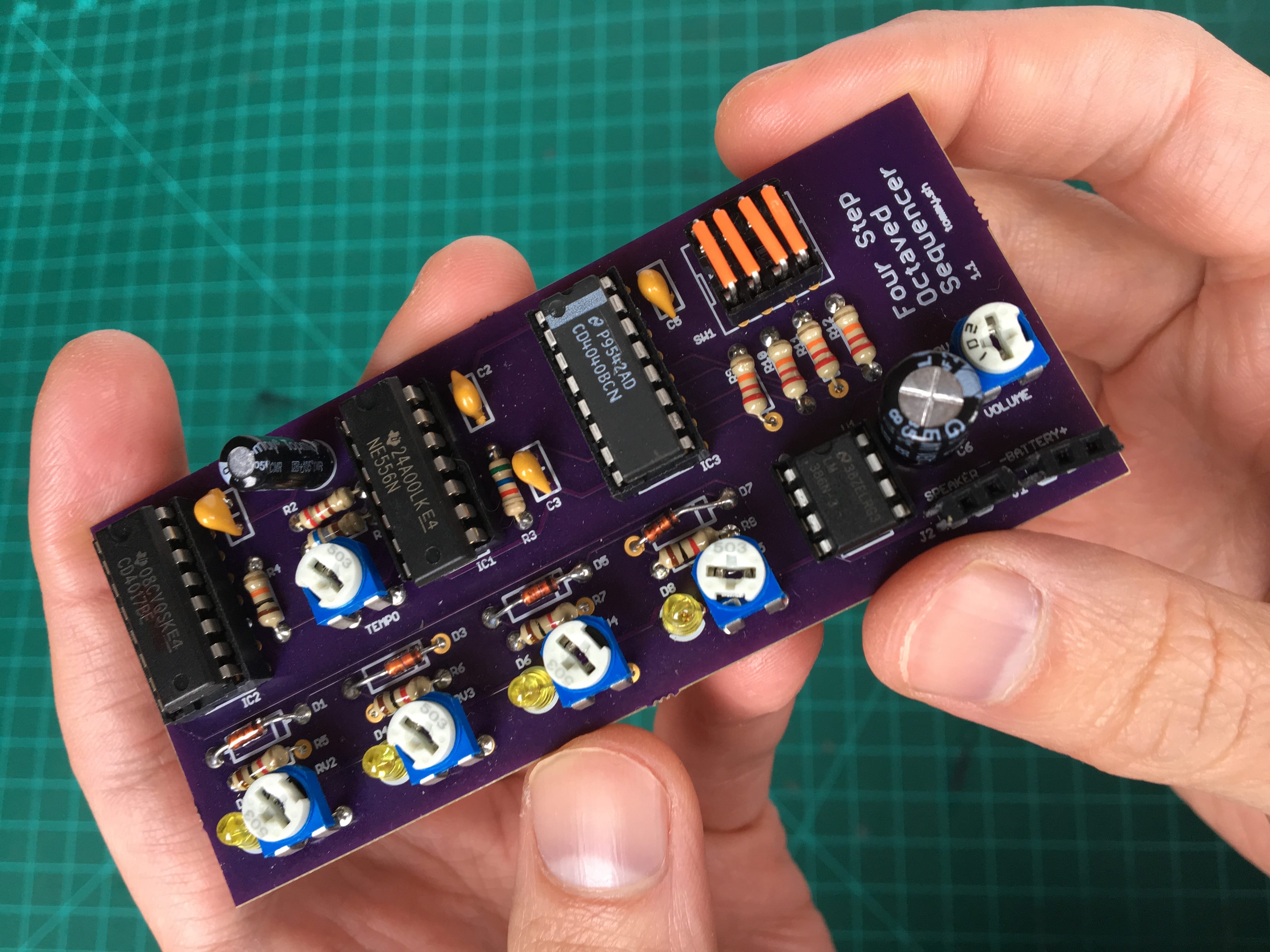
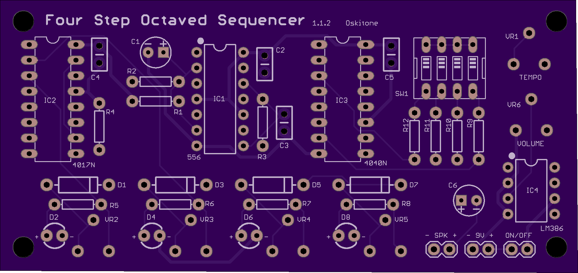
A couple months later, I designed a PCB version (my second PCB design ever) and had a handful fabricated. The only difference in the PCB from the original perfboard is that I increased its octave outputs from 2 to 4 and made them switchable.

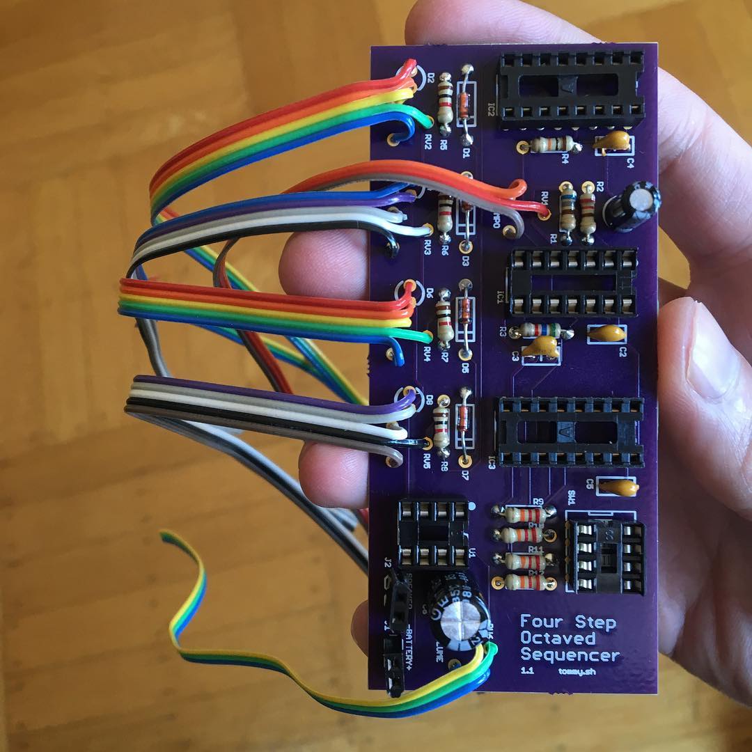
Check out the "tommy.sh" branding in the corner. This was before I before I'd decided on "Oskitone" and bought the domain name.
And PCB to product idea
Then I designed it into a 3D model, the subject of my post on bringing realistic animations to OpenSCAD.
Fast forward to today, where the subject of this post is the 3D-printed and assembled version of that model, which sat unfinished for months while I worked on the OKAY Synths.
In review
Signs of things to come
When making the OKAYs, I'd make a bunch of fit tests and prototypes before getting to a "finished" build. What's interesting to me about this sequencer prototype is that, because I spent too long designing it without printing any fit tests and then abruptly stopped working on it, it's a fully formed snapshot of what I was thinking about (warts and all) at the time.
And there are some fun parts about it that I really do like, a lot of which would make its way into my other work.
- Labels
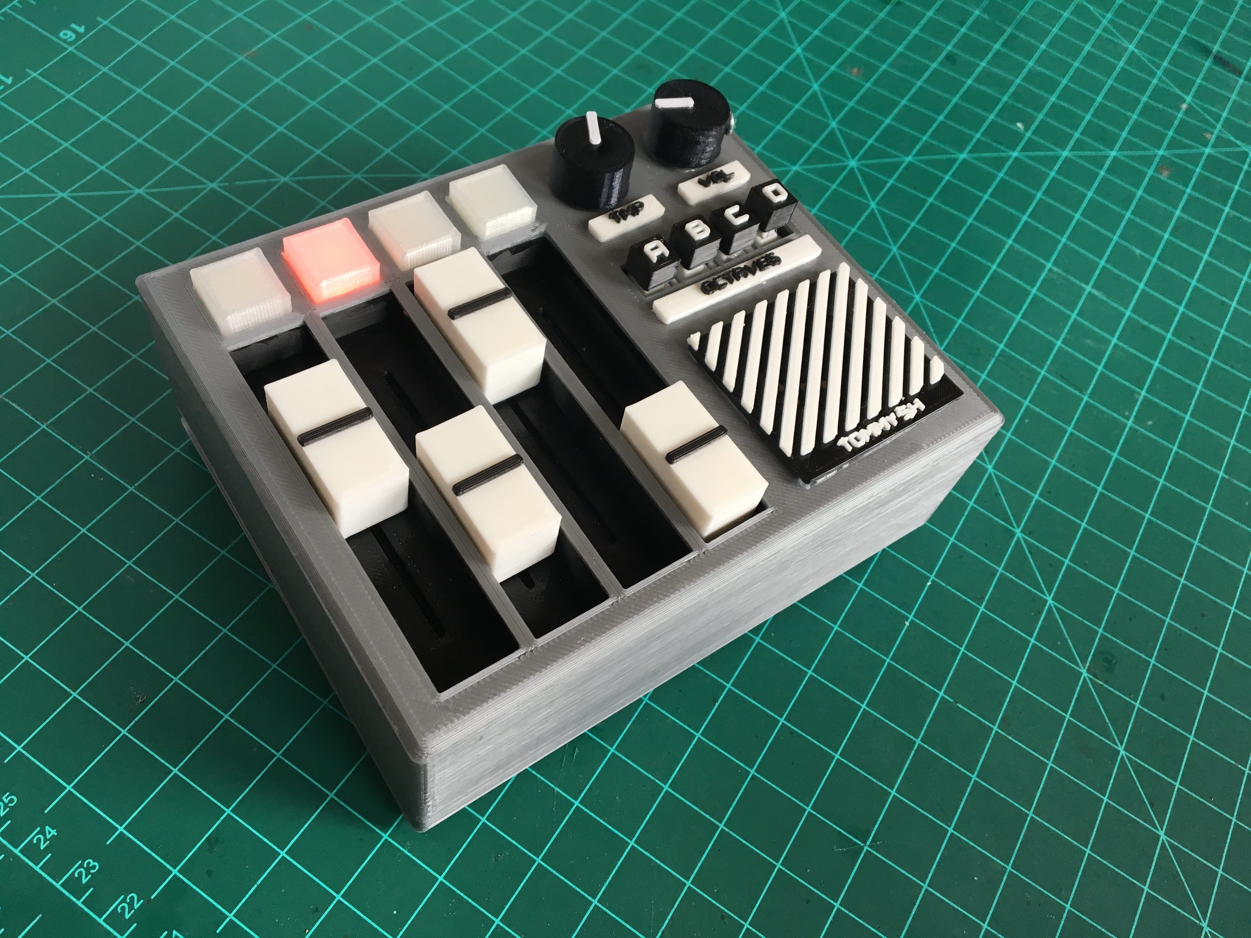
The tempo, volume, and octave controls have corresponding cute, little, 3D-printed label pieces. I've always liked this approach more than embossing/engraving text into the enclosure itself or using some sticky label tape. It's a physical, tactile thing that just makes me feel good. If you're working and printing in 3D, then I say go all out. - Multi-color print
Here's where I perfected the technique of changing filament midway through a print to get those sharp color changes, which I now use gratuitously. It's an easy hack that any printer can do. - LED light pipes
Each step has an LED pressed into a 3D-printed semi-transparent cube called a light pipe. Its dimensions are based on my experiments in designing light pipes. I'm sure I'll find another project to use this idea on. - Custom potentiometer knobs
These are the first time I made custom potentiometer knobs to fit D or smooth shaft pots. - Slider potentiometers
The original robot collaboration had a slider for tempo, and I liked it so much I made the four step pitches use them instead of knobs. Sliding is funner than turning, I think. Of course, I put custom caps on them. - Pushbuttons
The OKAY synths use a rotary switch to select just one octave, but it's technically possible to select multiple and mix them together. The sequencer does this with latching pushbuttons. Press once to add the octave to the mix; press again to remove it. They're capped with ABCD letter caps.
Hard lessons learned hard
Connections, glue, parts count
I wanted the enclosure to be able to be either 3D-printed or laser cut from plastic or plywood, so I designed it to have discrete top, sides, and bottom. That necessitated all internal supports to also be separate pieces.
And all of these things had to be glued into place with heavy duty industrial strength glue. This was a literal headache.
- Labels and speaker grill glue onto enclosure top's top
- The enclosure top's bottom glues to the enclosure sides
- The black slider base, speaker wall, octave switches platform, and knobs bases glue into the enclosure top
- Light pipes glue into slider base
- PCB glues into enclosure bottom
- Octave button caps glue onto buttons
Lesson 1: When designing for easy assembly, the priority of connection types should go snaps, then screws, then glue. Glue is the worst and should be a last resort. There is no glue in the OKAY 2.
Lesson 2: If you must use glue, have the pieces self-locate for effortless, perfect positioning without an external jig.
Lesson 3: Design with one type of manufacturing in mind. The enclosure would have been so much simpler as two pieces instead of three, and all of the supports could have been baked into it as well. Keep parts count low!
Enclosure closure
So the enclosure's top glues to its sides, but how does the bottom attach? With screws. And not very well.
The sides, which are one solid piece of four walls, have pocket wells for threaded inserts, which get melted into the plastic with a hot soldering iron. These take screws through matching holes in the enclosure bottom corners. I unfortunately got a trace amounts of melted plastic in the inserts' threads during installation, making them hard to screw into.
I also thought I could make a better fit by nestling a tiny lip on the sides to a tiny grooved cavity on the bottom, but it was too small to print well and basically just resulted in a tiny gap.
The end result is an enclosure that's hard to open and can't even close properly anyway.
Lesson 1: Make sure threaded inserts stay clean of foreign material. A good way for the design to help this is to have both ends of the insert's containing walls be open. If there's plastic at the opposite end, the soldering iron will pierce it and draw it back up into the threads.
Lesson 2: Integral features like the fitting lip grooves shouldn't be at a scale so small they're within the tolerance limits of the manufacturing machine.
Lesson 3: Make fit tests before making the whole thing!
Lesson 4: Users shouldn't have to disassemble a device to do routine work like change its battery. Make it easy to open and admire.
Space and size
The dimensions of the instrument were derived from the dimensions of the components. Four pushbuttons set the width of the side control panel, which set the knobs's diameters and speaker size. To make it worse, I also didn’t factor in vertical room for cables, so the whole thing is jam packed and can hardly close.
It is a needlessly tight and finicky fit. Seemed like any time I touched it during final assembly a new thing would break.
Oh, also, the small knob diameter meant that the volume's tightening screw sticks out. I hadn't considered that before printing the whole thing.
Lesson: Make room! Make room!
"Musicality" (aka "musical utility")
Potentiometers have some natural variance in their resistance, just because of the way that they work. For most typical uses, like, say, a volume or pan control, that ~5% variance is an unnoticeable non-issue. It is, however, very noticeable when they're used for something that requires high precision like frequencies for musical notes and even more noticeable when used adjacently -- controls that seem to be in identical positions should have identical effects.
The sequencer's pitch oscillator uses resistance supplied by slider potentiometers to determine frequency. It's fun but imperfect, making the instrument more about noise than music.
Lesson: Musical instruments need to keep tune and be consistent.
Sound
Ugh, why is this little speaker so pitiful? Even if I boosted the amp, you can hardly hear any bass.
And at volumes higher than 50% the octaves don't mix evenly. The low octaves basically override the higher ones. My naive mixer of resistors was, indeed, naive.
Lesson 1: Bigger speakers are better speakers.
Lesson 2: Multiple sounds want multiple amplifiers.
What's next?
Someday I'll clean it all up and have some kind of sequencer project on the Oskitone store, but it won't be this one. This one will go on my shelf as a reminder of how far I've come.
In the meantime, I've got a couple of the "tommy.sh" branded PCBs left. Holler if you want one.
Update April 5, 2018
I put the remaining handful of prototype PCBs on the store, promptly sold all of them, and am ordering more.
If you want the STLs to 3D-print your own just like the prototype, that's not a great idea! As this blog post attempted to explain, the design has way too many problems for me to feel good about putting my name on it and telling other people to make it.
Stay tuned!
Update January 17, 2021
Open-sourced the PCB: https://github.com/oskitone/four-step-octaved-sequencer
Update March 12, 2026
...and made its OshPark project public so you can buy the PCB direct from them with my blessing: https://oshpark.com/shared_projects/xo5nRkSm