Designing Potentiometer Knobs
Who needs to buy new potentiometer knobs when you can make your own? Armed with patience, calipers, and a 3D printer, this is quite doable. (Note: this advice will also apply to rotary switches and encoders!)
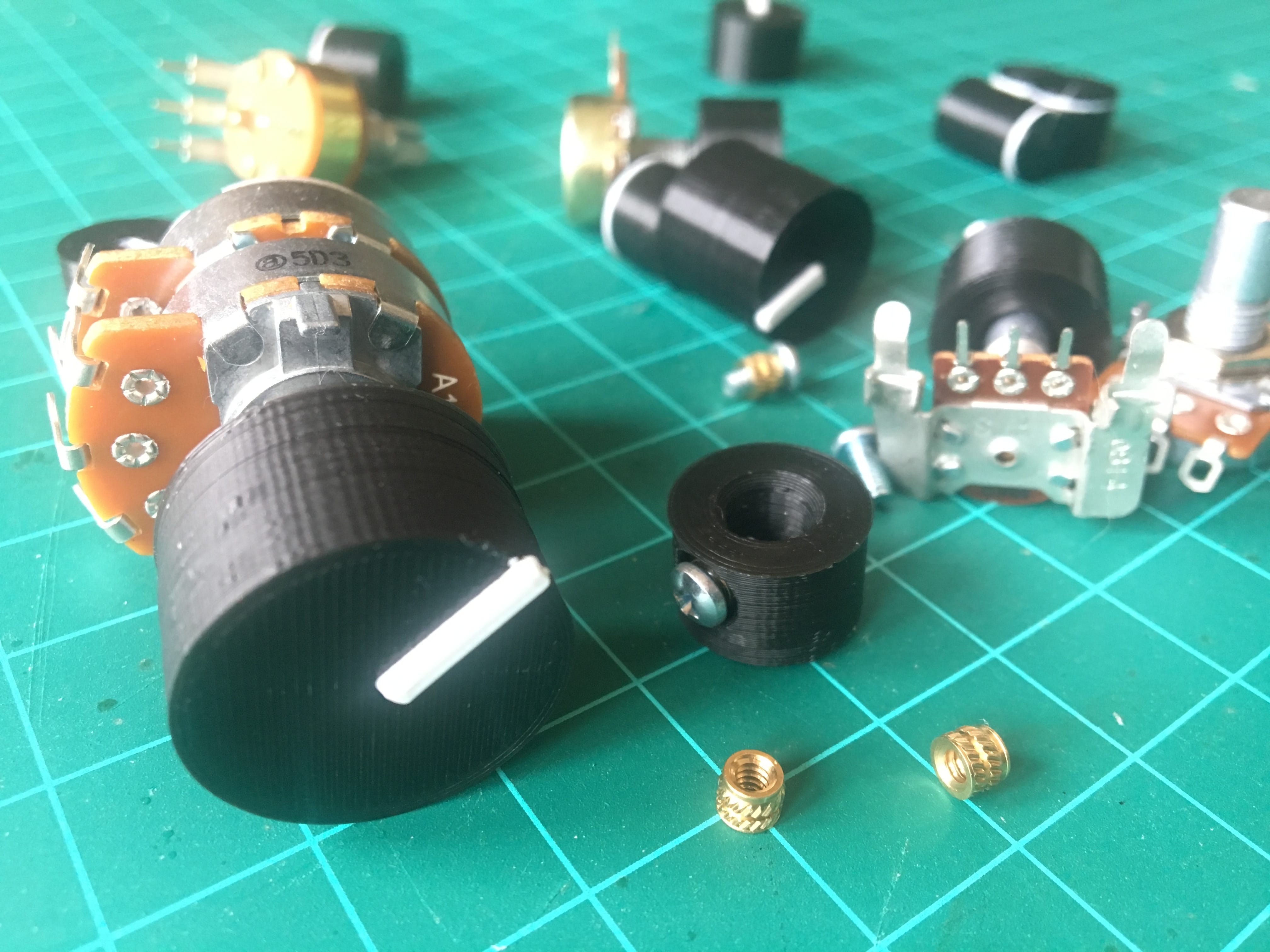
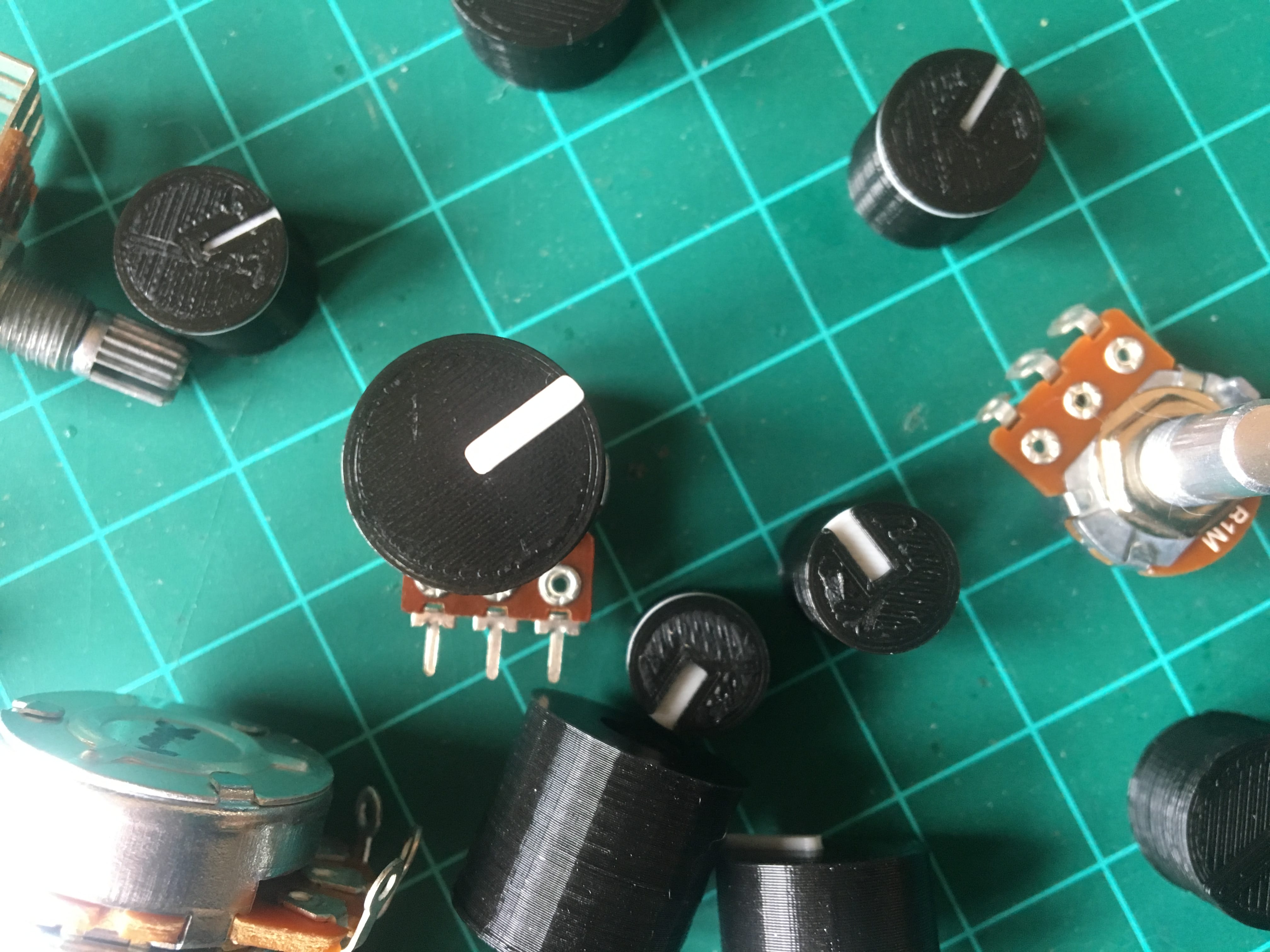
Different knobs for different potentiometer shafts
A well-fit knob matches a potentiometer (affectionately referred to as “pot”) and its shaft. Thankfully, there are only a handful of types:
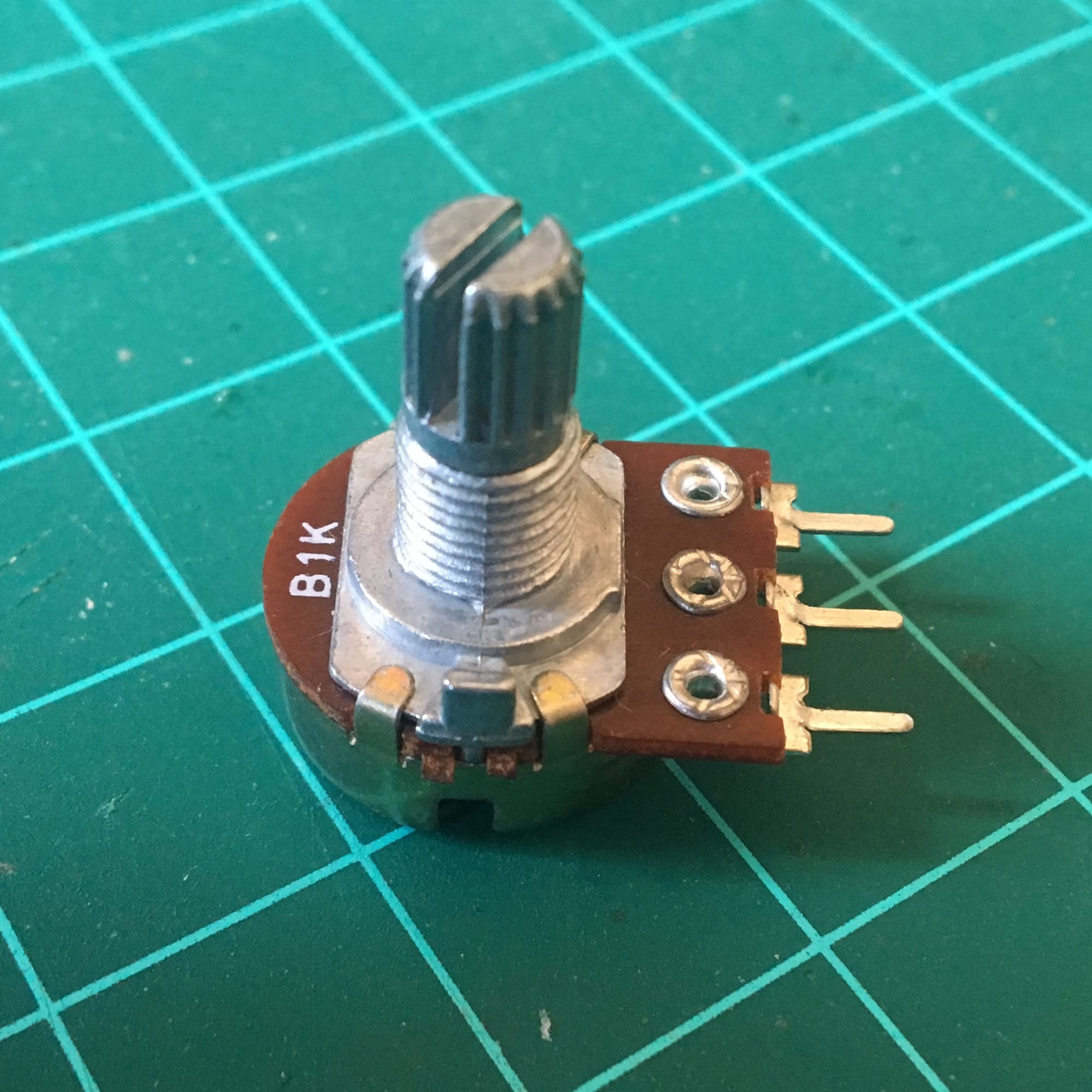 |
Splined / Knurled This type of pot has vertical grooves lining the outside of its shaft. These ensure a solid grip with whatever’s mounted to it. |
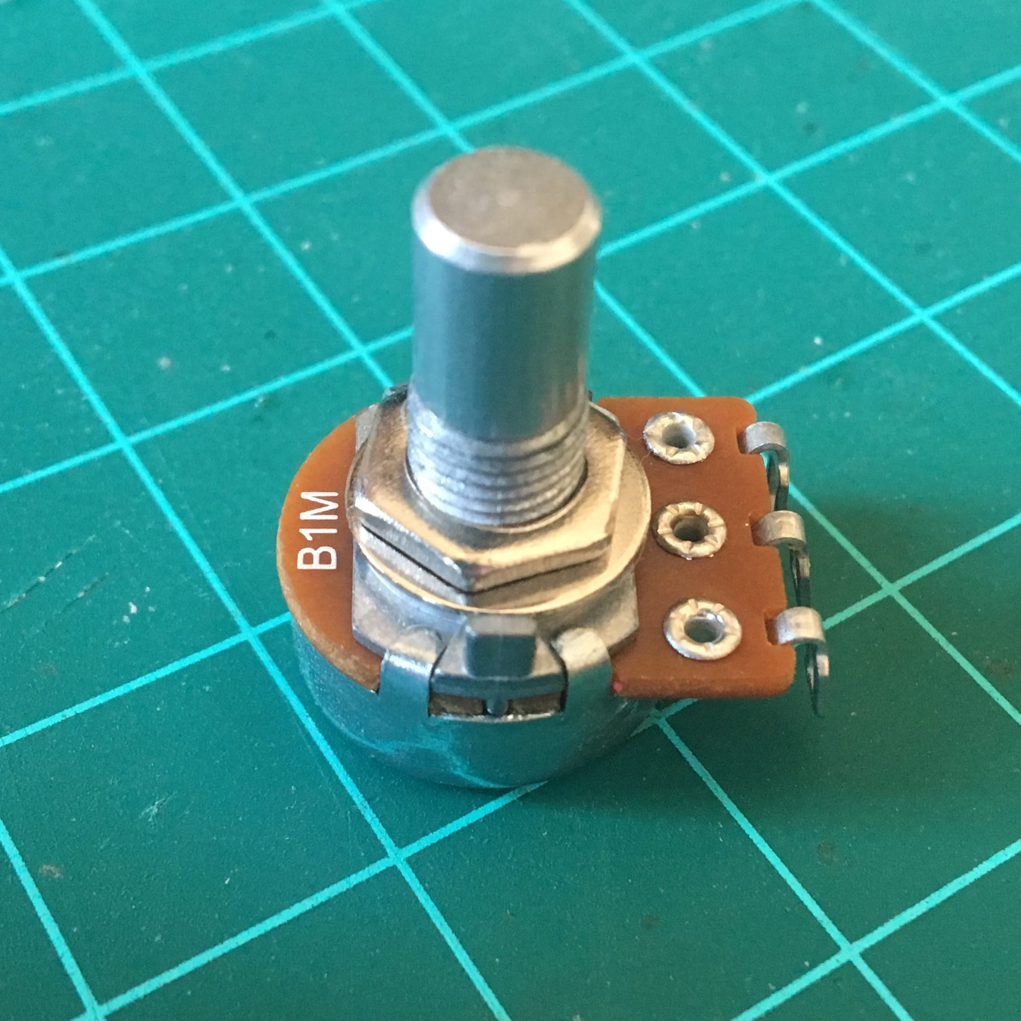 |
Plain / Solid No features on this type, just a clean cylinder. |
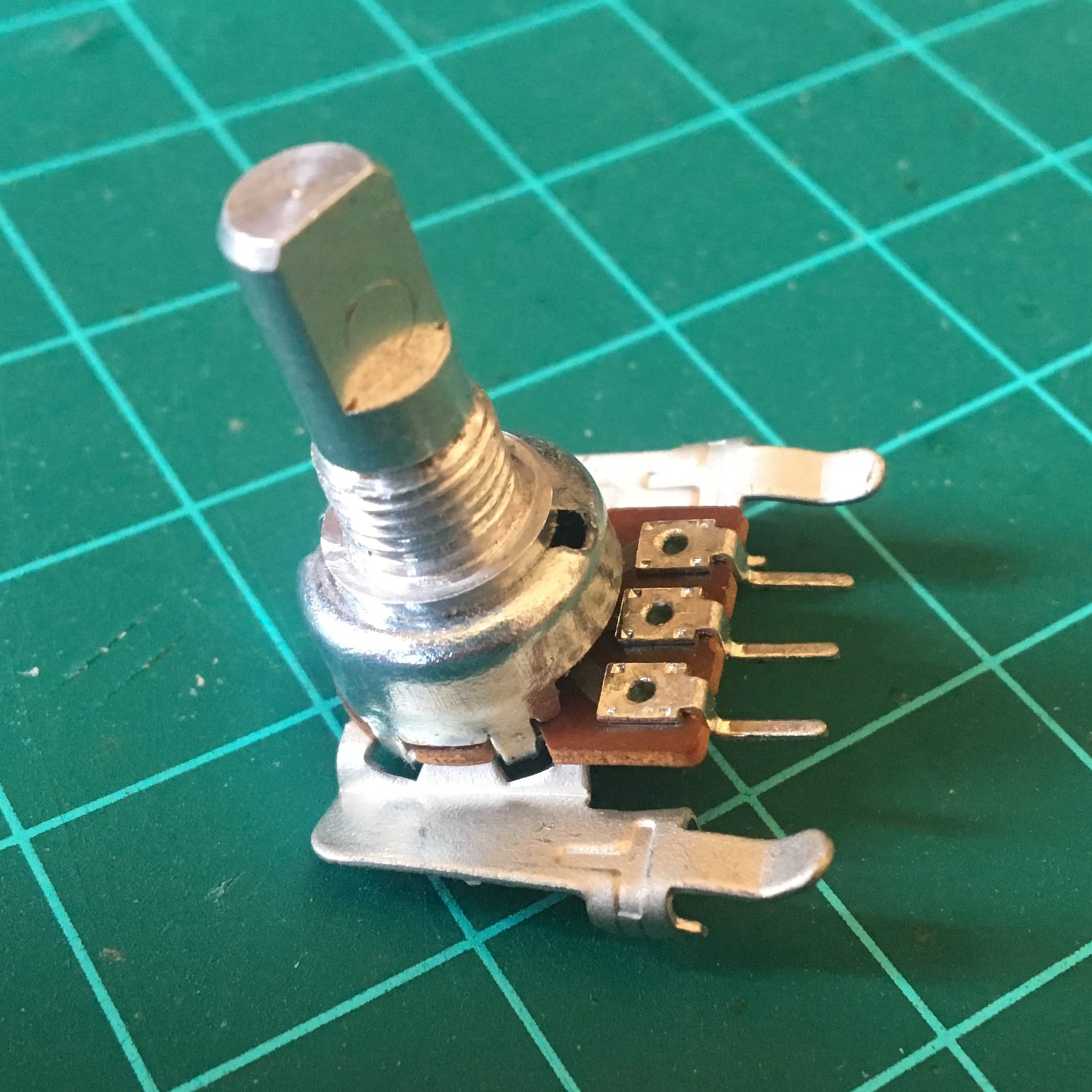 |
Flatted / “D Shaft” These are like the plain shafts but have a cutout. When viewed from the top, they make a “D” shape. |
Why would anybody even want to "reinvent the wheel" when commercial potentiometer knobs are plentiful and readily available?
- Control uniformity
A project may use different types of pots side-by-side, each with different dimensions or shaft types, and fitting store-bought knobs may not match. By making knobs that internally match different specifications but have identical outward appearances, you can abstract away the underlying technical differences and have a consistent interface for the user. - Custom position markings
I recently made an instrument with D shaft pots, all mounted at odd angles to the enclosure, and I wanted their “0” positions to point in a way that my store-bought knobs wouldn’t allow. By making my own, I was able to have a custom rotation degree that wouldn't otherwise be possible.
And, of course, there’s always “it’s fun to understand how things work by making them”, which is usually the only excuse that I need.
Basic design
The simplest theoretical potentiometer knob is 1) a body with 2) a cavity for the shaft and 3) some way to mark position.
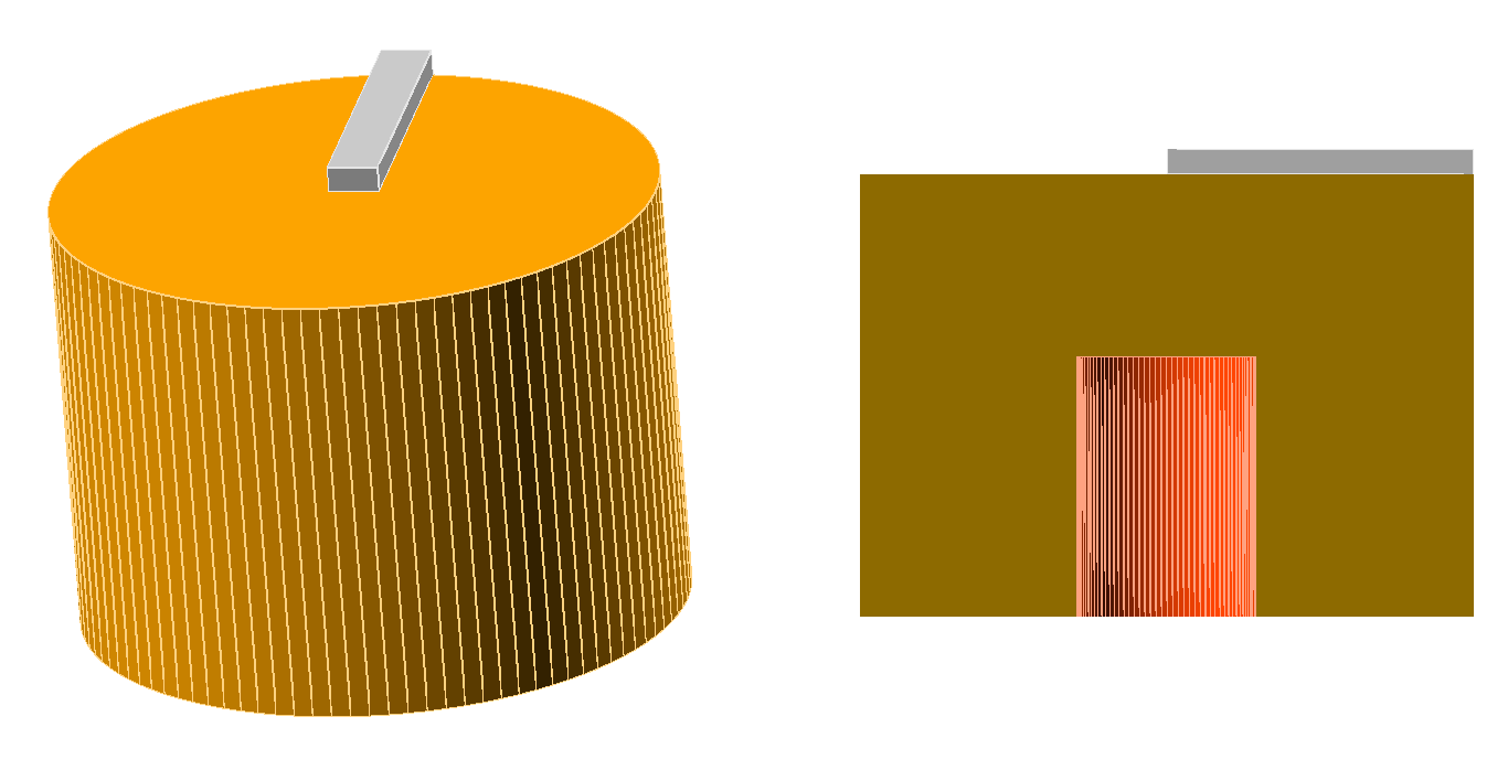
All the following examples fit that basic archetype but improve upon it to suit their respective shaft types.
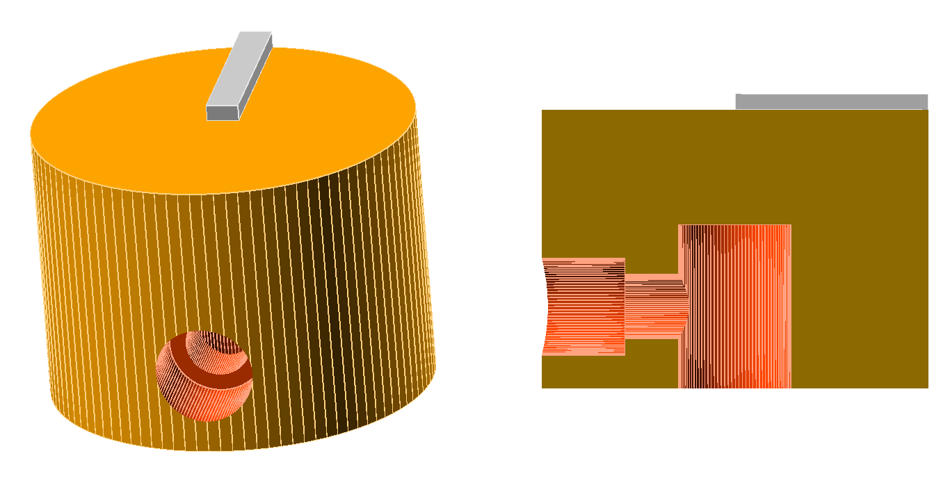
Splined
The splines on these shafts need something to hold onto. Supply that with “shims”, thin strips of sacrificial material that wedge between the splines to hold the knob in place.
With enough shims, you can effectively make a negative model of the pot shaft and its splines, but an odd handful is more than sufficient and resilient to different spline counts.
One caveat about this approach is that the shims will wear out as its moved to different pots or reapplied to new rotation degrees.
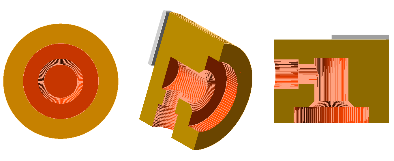
Plain
Without something to hold onto, the shims from above won’t work as well here.
Instead, loosen the inner fit but tighten externally with a machine screw and threaded insert. The inserts I used were made specifically for thermoplastic, and assembly is as simple as pushing the insert into its cavity with the clean tip of a hot soldering iron.
Unlike a typical wood screw, the machine screw has a flat end to butt against the shaft, and the insert will hold the screw without stripping the plastic, even after repeated positioning and tightening.
For a flush look, if the wall is deep enough, match the insert cutout’s depth to its height and widen the remainder of the cavity to fit and hide the screw’s head. The screw will otherwise stick out, which may be a look that you like anyway.

Shims aren’t a bad idea here but aren't absolutely necessary. The tension screw is doing most of the work.
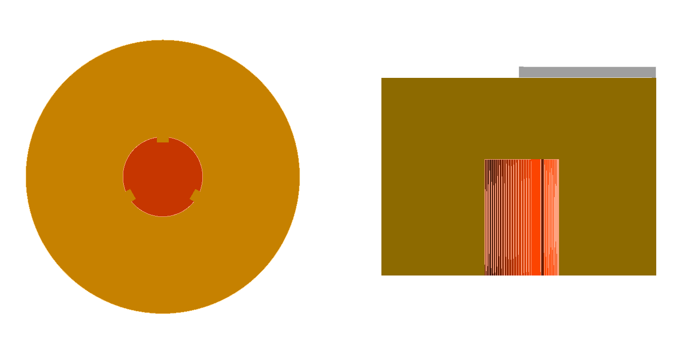
Flatted
This one’s easy enough. You’re essentially making the negative of the "D" shaft.
The advantage of a flatted knob is that rotational force is applied directly to the shaft without fear of stripping plastic, screw, or shaft itself. Supplement tightness with shims or a tension screw.
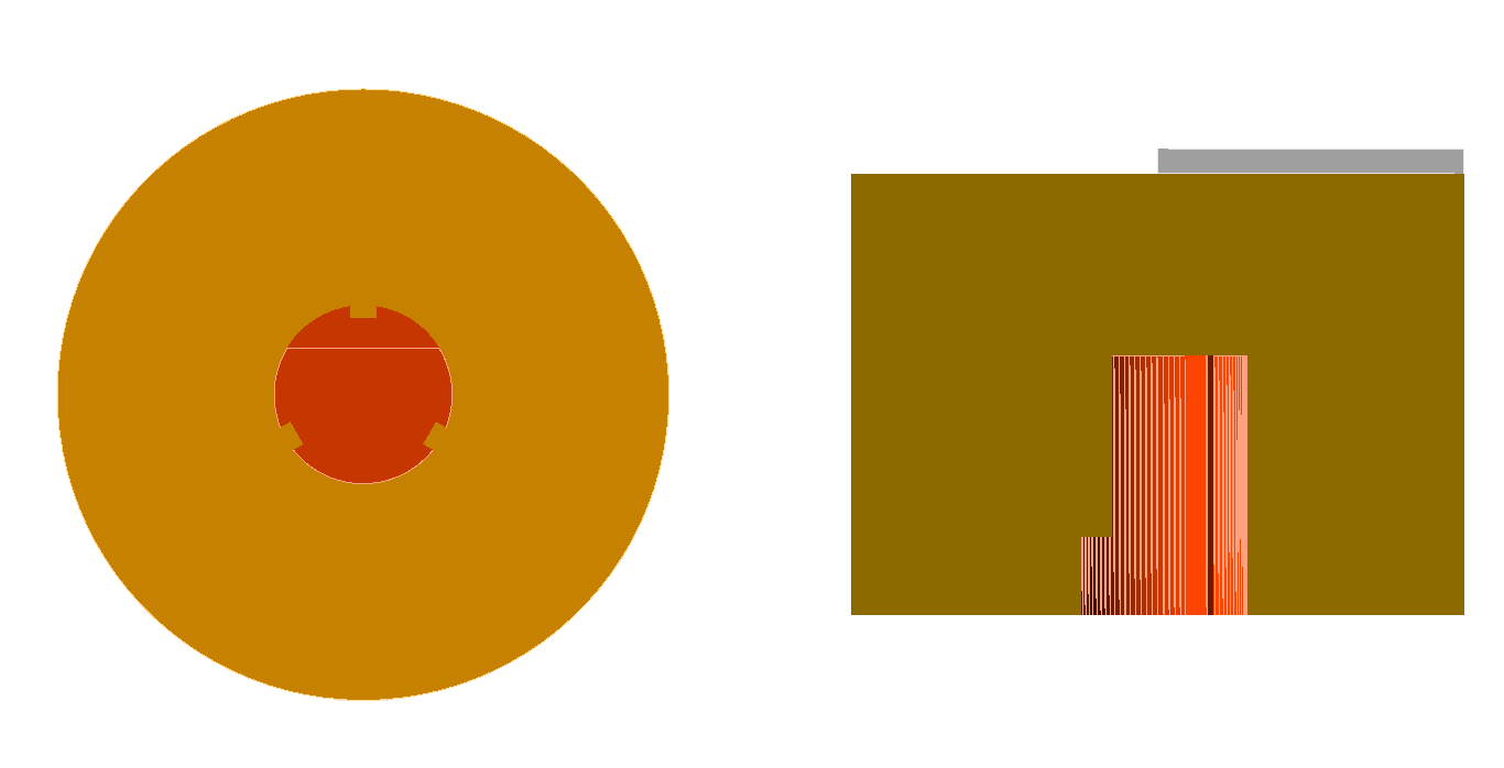
Mounting concerns
You’ll notice two things if you try to print one of the above examples and push it onto a pot:
- Even if the inner diameter perfectly matches the shaft, it will be almost impossibly tight when you first put it on. Counteract that with a 45° entrance slope called a chamfer. I used this same technique for LED light pipes.
- Depending on how it’s mounted, there can about a ¼” of vertical space from the pot’s fastening washer and nut below the knob, making it look like it isn’t pushed on all the way. If the knob is wide enough, you can get rid of that vertical space by providing a recess cavity for the mounting hardware.
Marking position
With the fit snug and securely tightened, the only remaining requirement for a pot knob is to let the user know how “turned” the pot is. I do this with a simple bar in a contrasting color.
And there you have it, custom potentiometer knobs!
You can download the OpenSCAD pot_knob() module I used for this post’s examples here. Please let me know if you find it useful or have any questions or suggestions.
Updates
Update November 21, 2022
Fixed missing standard_pot_flat_cutout module in the knob.scad OpenSCAD code. Thanks for the headsup, Ross!