Scout
It's time for a new Oskitone synth... the Scout!
It's called the "Scout" because it's the first Oskitone synth to use a microcontroller, specifically the ATmega328 -- just like the Arduino Uno.
From the readme:
scout (/skout/):
- One sent to obtain information
- Jean Louise “Scout” Finch, of Atticus Finch
- The first synth from Oskitone to venture into the big ol' world of microcontrollers
The Scout is:
- Beginner-friendly: All components are through-hole (instead of surface mount) for easier soldering, and full assembly takes about 45min. Standalone, battery-powered, doesn't need a computer or external speakers to work. Fun!
- 3D-Printable: Besides the electronics and nuts and bolts, all parts are 3D-printed. And with a total width of ~160mm (about 6.3"), the Scout can fit on smaller, "Mini" (18x18x18cm) size print beds.
- Hackable: Arduino-compatible and fully open source! Hook up an FTDI Serial TTL-232 cable (sold separately) to update its code using the Arduino IDE.
- Minimally featured: 1.5 octaves of keys, a volume knob, on/off switch, speaker, headphone jack. Monophonic square wave with fixed glide and octave.
In addition to it being the first microcontroller-controlled instrument from Oskitone, the Scout would also make a fine introductory DIY instrument for the budding electronics hobbyist. (Some experience soldering and a general familiarity with how electricity works are recommended though!)
Like my previous work, I designed the Scout's PCB in Kicad and everything else in OpenSCAD, specifically for 3D-printing. The Scout is available assembled or as a DIY kit, with and without the 3D-printed parts; and it's fully Open Source!
This blog post is a semi-deep dive into why I made it, how it works, and its features and how they were decided.
Chasing product/market fit

Where the POLY555 looked complex and was complex to put together, the Scout tries to do the same but at the other end of the spectrum: look simple and be simple to put together. Its target demographics are folks new to electronics, parents looking for a fun project to do with their kids, and STEAM class educators and workshoppers — all demos that I'm not currently serving well for piano-like instruments. (Which takes the APC out of the running. Sorry, APC!)
Defining that target upfront meant gleefully stripping away requirements wherever I could:
- Instead of 555 timers or complicated analog circuits for the oscillators, it's all software. There're way fewer discrete components to solder, no byzantine schematics to scratch your head over, and absolutely no manual tuning of notes like on Oskitone instruments of yore.
- More piano notes is great but it necessitates both more stuff to solder and a bigger 3D-printer to fit all of them! I narrowed the key count to the max that would fit on very common 18cm wide printer beds.
- I prototyped but abandoned controls for octave and glide. Instead, they're pulled to the top in the Arduino code and made to be extra inviting to experiment with.
- Similarly, there're no controls for other typical synth options like wave type, filter, envelope, etc. Arguably those operations are what make a synth a synth, but they're unnecessary for the target demo. Also no MIDI or Control Voltage support. Ditching all of that leaves out technical and cognitive complexity.
In startup parlance, the Scout is a Minimum Viable Product. I hope people like it, I hope it inspires them to play around with electronics and code and music, and I hope it will serve as a good foundation for me for future Oskitone synths.
How does it work?
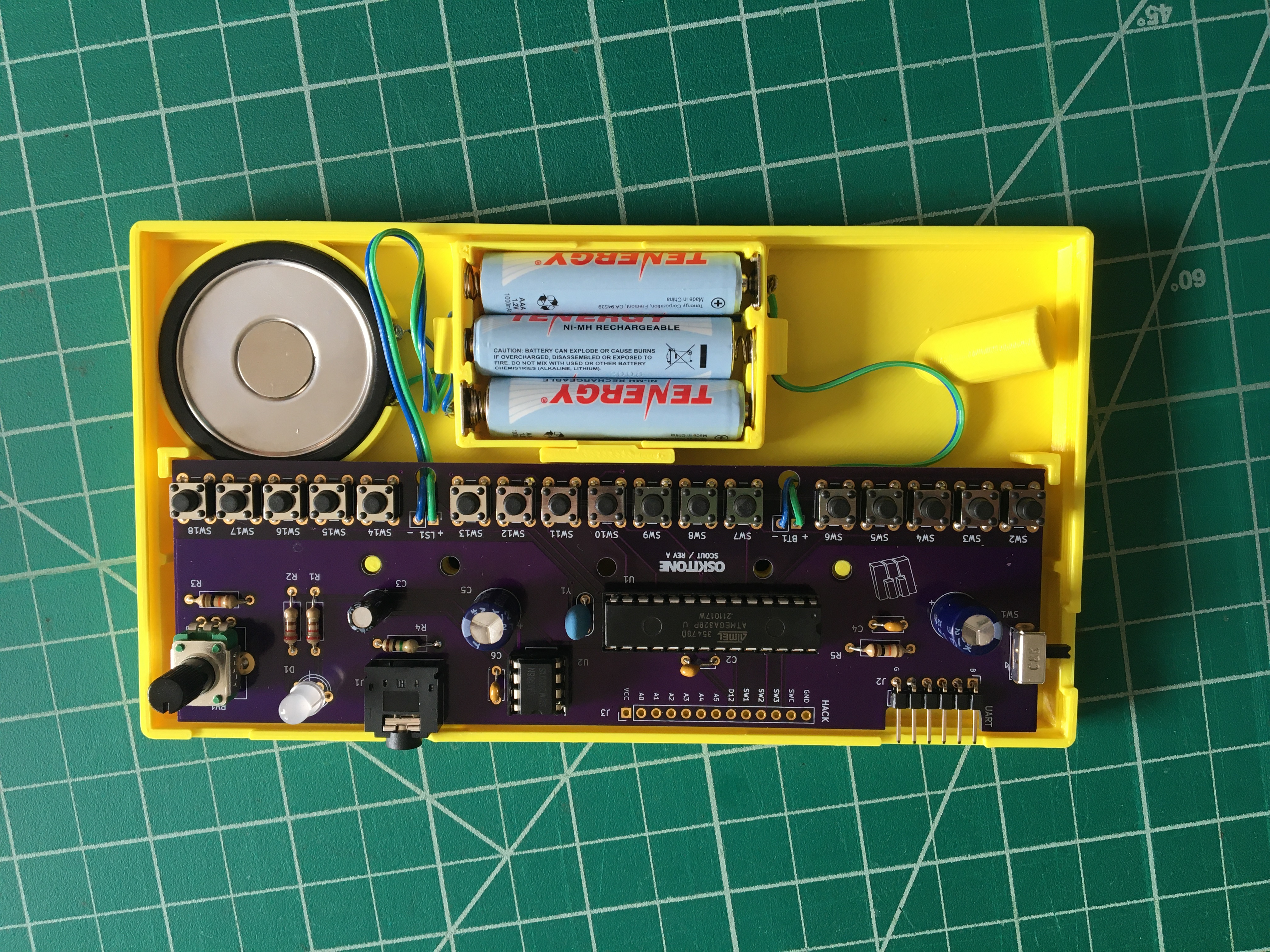
Electronics
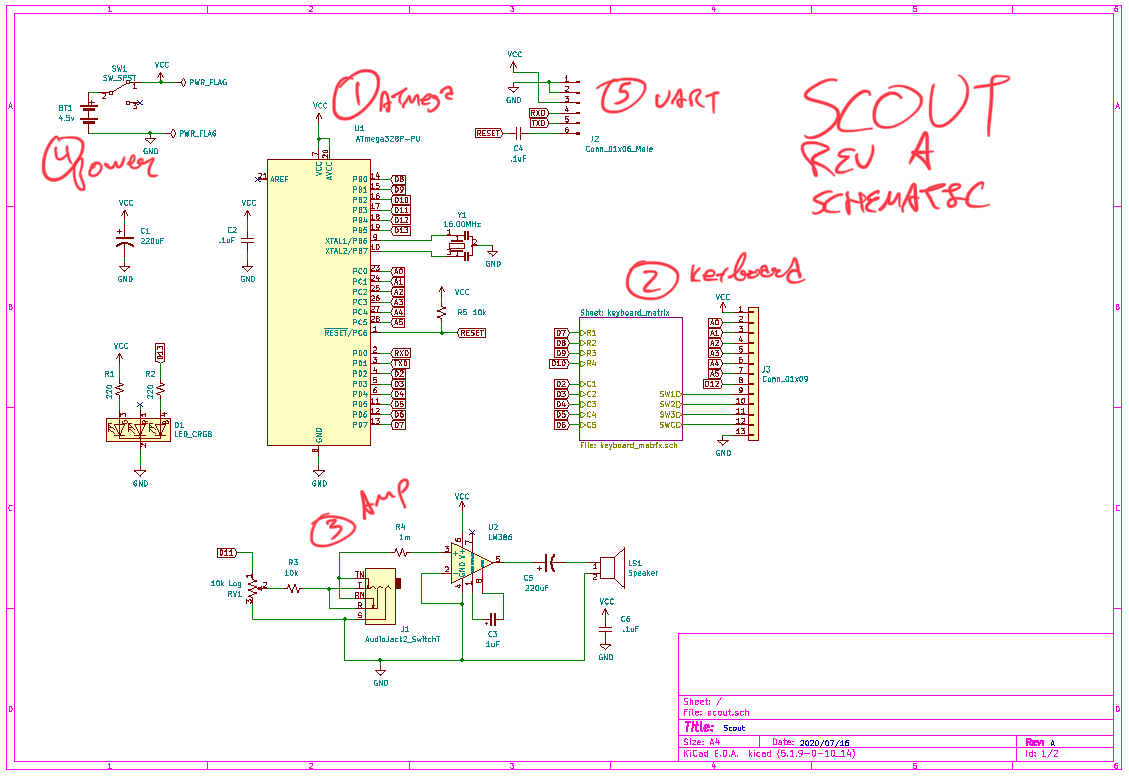
- The heart of the operation is an ATmega328 microcontroller. It's programmed to play a simple tone and light an LED whenever a key is pressed.
- The 17 notes' keys are mapped to switches that are set up as a matrix. (Instead of using 17+ GPIO pins they only use 9 [4 rows of 5 columns = 20 possible keys]. There are drawbacks to this approach but none that matter for a monophonic instrument.)
- The tone from the microcontroller goes through a potentiometer for volume, a headphone jack for audio output, and finally to an LM386 amp chip to drive a small speaker.
- Power for the ATmega and LM386 is supplied by three AAA batteries.
- A UART header allows for uploading new code to the ATmega328.
All of that is reflected on the schematic:
And the PCB:
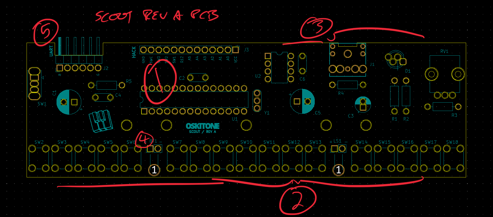
To encourage hacking, the ATmega's unused pins are pulled onto an unpopulated "HACK" header. There's one digital pin, five analog, two unused switches from the keyboard matrix, plus VCC and GND.

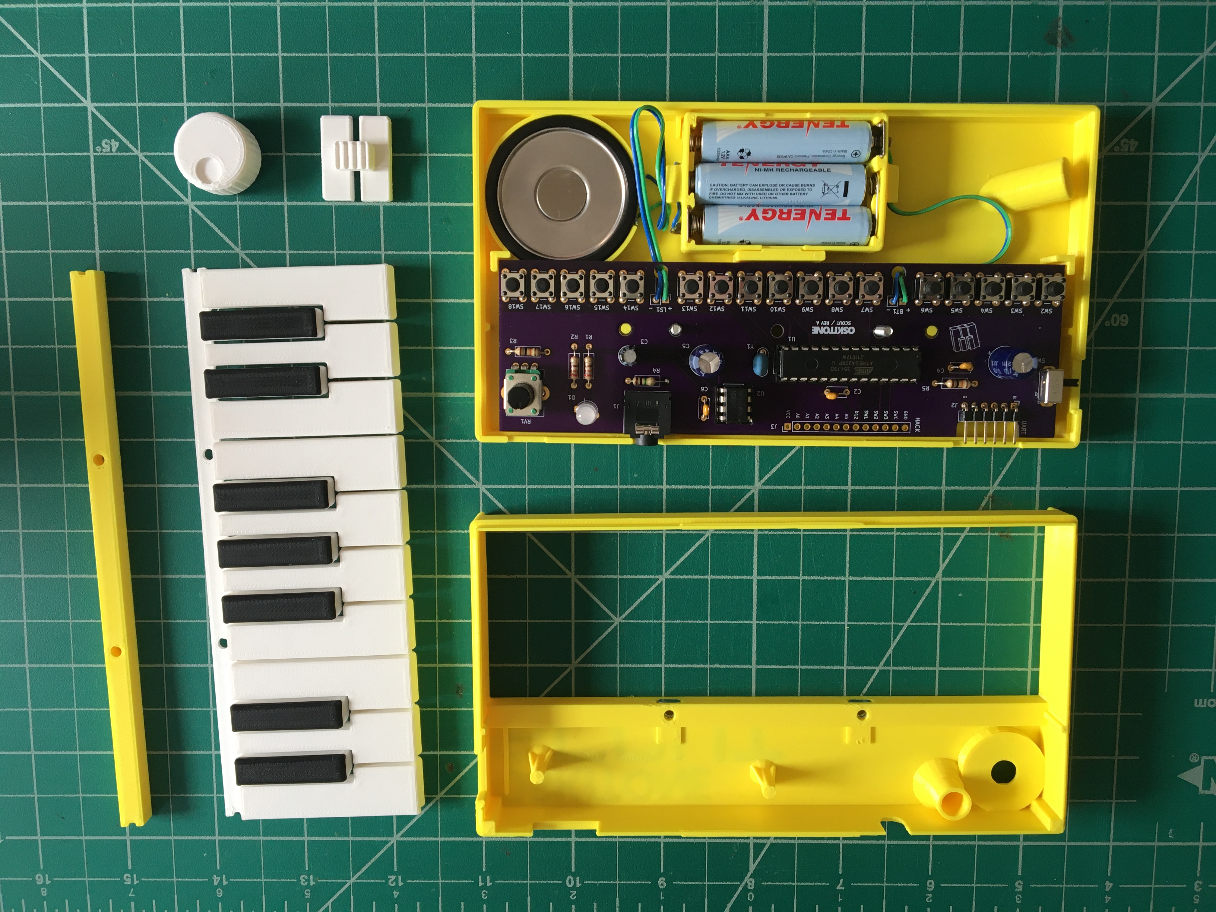
3D-printed parts
The electronics fit snuggly inside a snap-together enclosure, along with keys and some other odds and ends, all 3D-printed.

Battery holder
All previous Oskitone machines used 9v batteries, but 9 volts is too high for the ATmega328 and would require a regulator to bring it down, costing more BOM and space. The Scout instead uses 3 AAA batteries for power, in a custom container that clips into the enclosure.
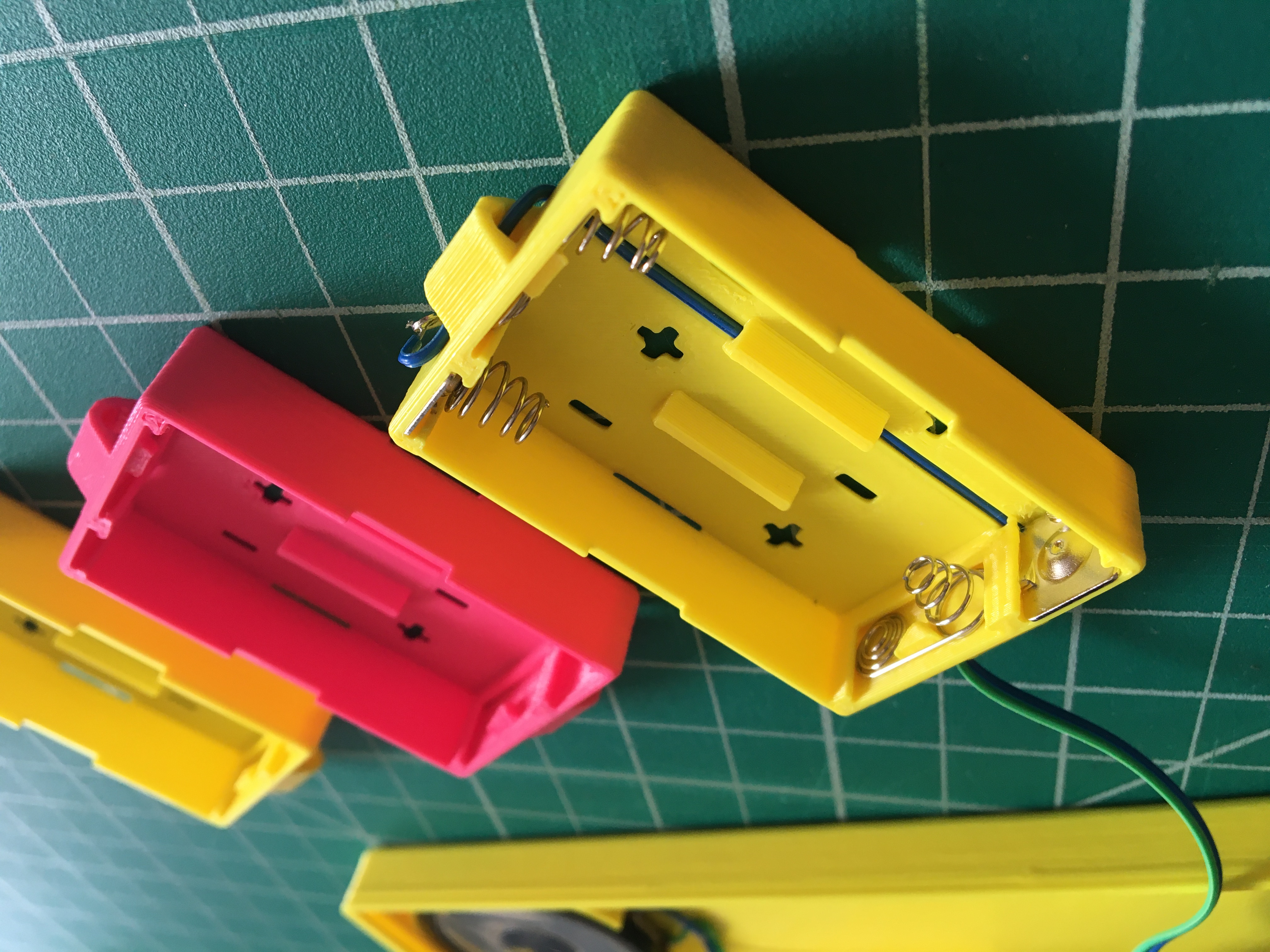
Making this was fun! I'd never paid much attention to how batteries fit into things before, but all the battery-powered devices in my house got a new level of scrutiny while I was designing the Scout's.
Sure does make me want to spin off a custom battery pack company!
(For those curious, AAA was chosen over the more typical AA for size reasons, as 3 AAs would be a little too big to fit under the keys without making them longer, which I tried but didn't like. There're also off-the-shelf battery containers that I could've used and did prototype with, but they also have size and cost caveats.)
Enclosure
The enclosure expands on those of previous Oskitone projects, with some humble upgrades:
- In addition to the screws through the middle to hold everything tightly together, the two halves snap together on the sides, cutting down on metal hardware and obviating trickier printed closures. Fine-tuning this took awhile but was worth it. It's very satisfying!
- The big, gratuitous text engraving technique is borrowed from the POLY555 and APC. For the label text near the volume knob and on the sides, a new "placard" style engraving prints better and more legibly at small font sizes.
- The "pencil stand" feature from the OKAY2 and POLY555 has resurfaced, with a minor upgrade for better fit. Jam a writing utensil in there to prop the Scout up for display.
- The enclosure top prints upside down with its face on the print bed. To support the front lip under the keys, there's a breakaway support built into the model.
- The front inner lip facing the keys has a rail that acts as a key endstop, hopefully preventing extra damage to the keys when they're played aggressively.
- Hidden components! The speaker sits under the keys and uses the them like a speaker grill, and the LED shines through the enclosure top.
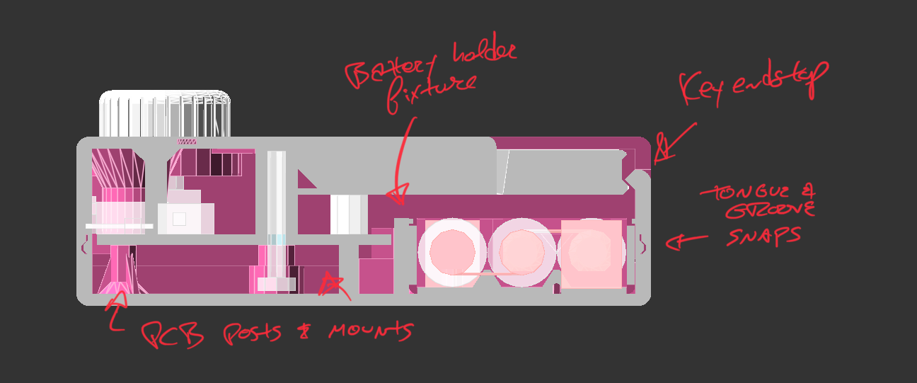
Abandoned enclosure ideas
One of the biggest things I worked on for the Scout was how to make its enclosure assemble more easily and look better than the POLY555's but without losing any of the structural/mechanical integrity needed for the keys. It's a difficult thing to get right and hard to articulate in words, but it's funny how hands kind of intuitively know when something doesn't feel good.
An early prototype design:
- I tried earnestly to make the enclosure like the APC's and have it slide together with tongue-and-groove joints, but it was complicated by the fact that the batteries/speaker and PCB had to be wired together but attached to different halves.
- I also tried thicker walls, thinking they'd make for stronger joints. But they were so strong that they lacked the necessary material "give" to bend, needed for the snap. Good lesson!
- That green rectangle was going to be a lightpipe for the LED, a perennial but elusive idea. Also tried circular and heart-shaped exposures for the LED.
- I did briefly have the power switch on the enclosure bottom like the POLY555 but abandoned it for aesthetic reasons.
- To let folks know the battery size and count before they pop the Scout open, there was briefly a "AAA*3" placard engraving on the bottom, before I removed it for not being worth the potential print failure (that small text is the easiest part of the print to mess up).
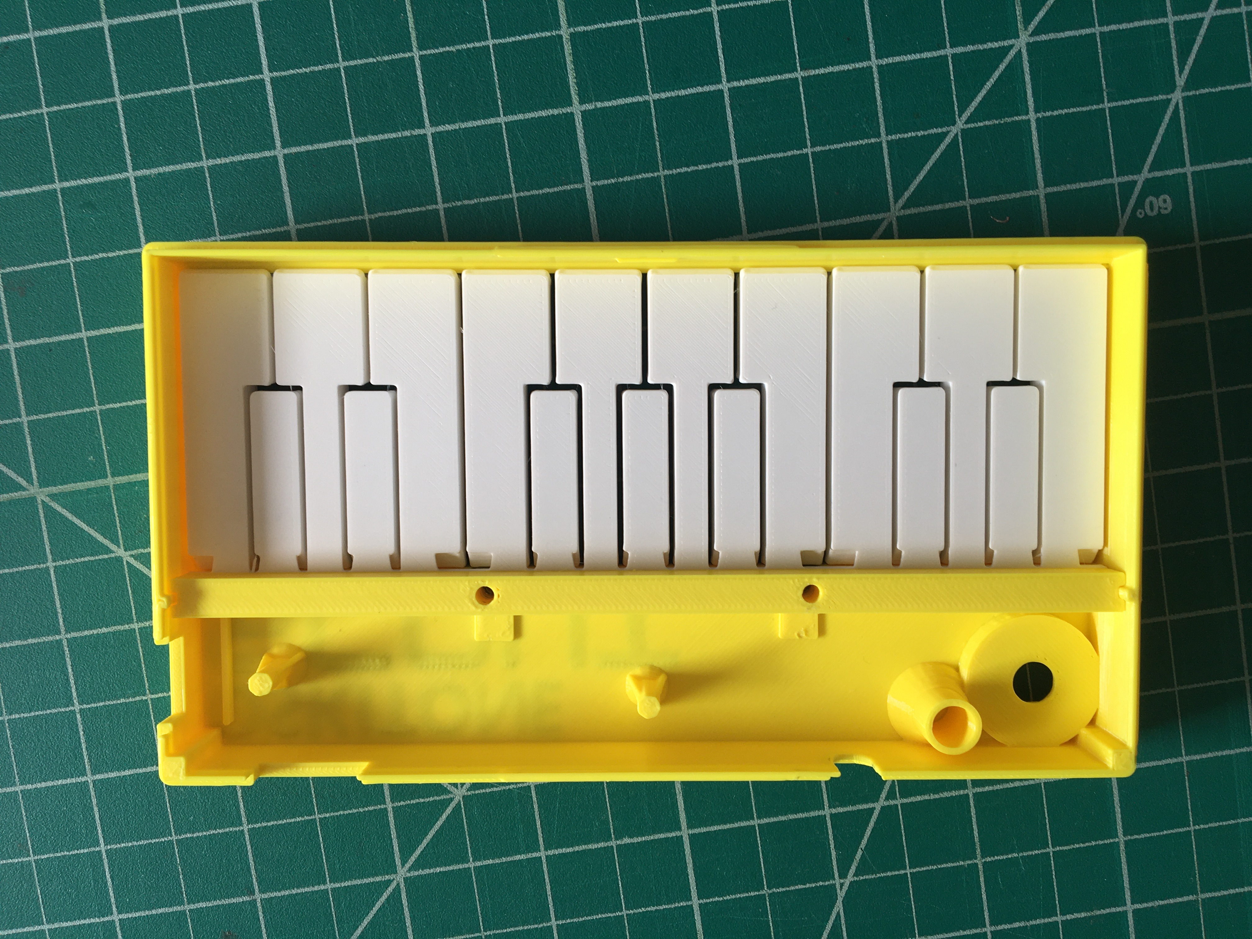
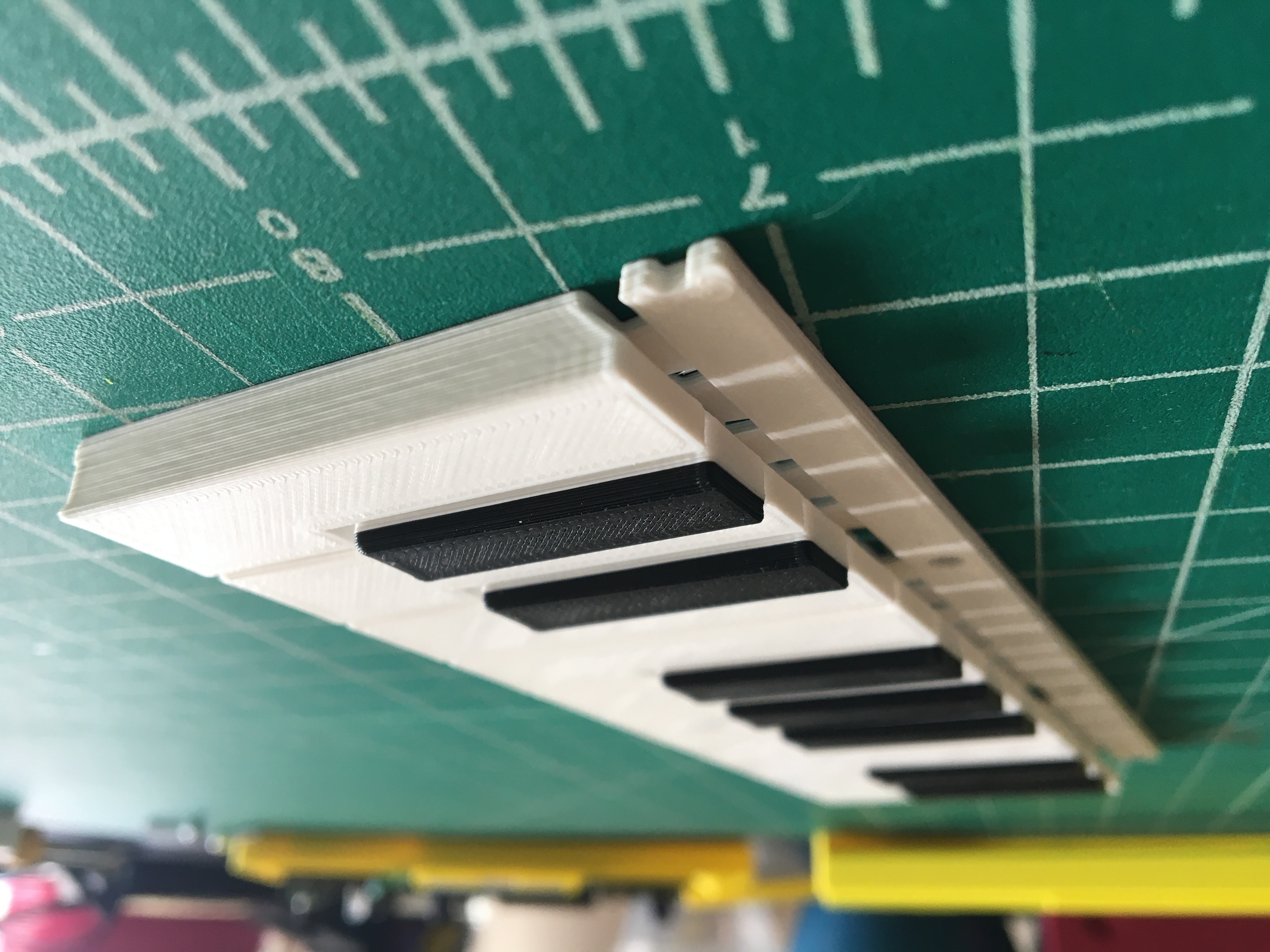
Keys
The keys work the same as they did in previous instruments, and dimensions mostly match the POLY555's, despite myriad experiments. If it ain't broke, huh?
With the enclosure top off, we can get a good look at how the keys work with their switches.
Physics teacher voice: Those pieces together form a lever, allowing the user to actuate a switch with a fraction of the force that would be needed if pressing it directly. Basically, the closer the switch (the load) is to the end of the key (the fulcrum) and away from where the user presses down (the effort or force), the lower that fraction, expressed numerically in a unit called a Mechanical Advantage or MA.
A cantilever, which is a narrow bridge of material between the key block and the mounting rail, helps it to bend at the right place.
It continues to be remarkable to me how the slightest variation to this tiny little piece of plastic multiplies its effects to the user. Too thin a cantilever and the keys are loud and feel cheap. Too thick and they're silent but hard to press. Tenths of a millimeter make all the differences. Fine-tuning it is patient, patient work.
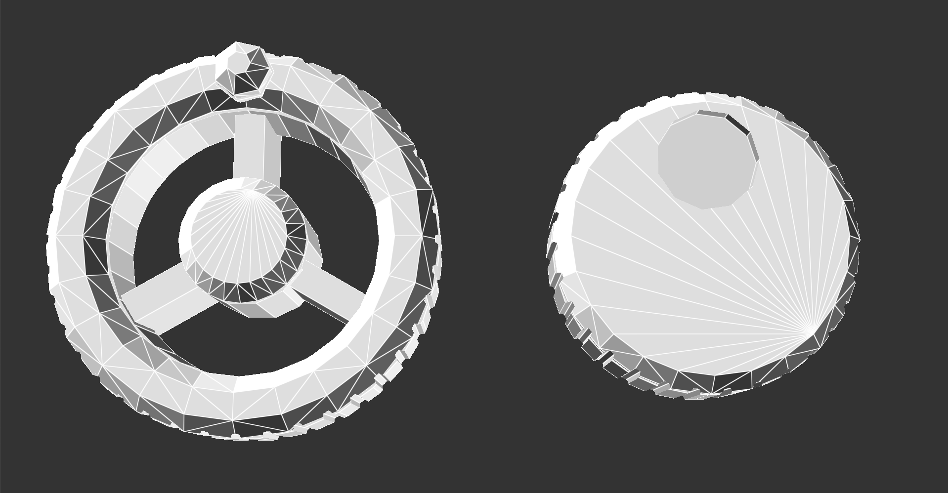
Volume knob
The Scout's lone control is its volume, adorned with a simple knob that's thoughtfully recessed into the enclosure and an accompanying "VOL" placard label.
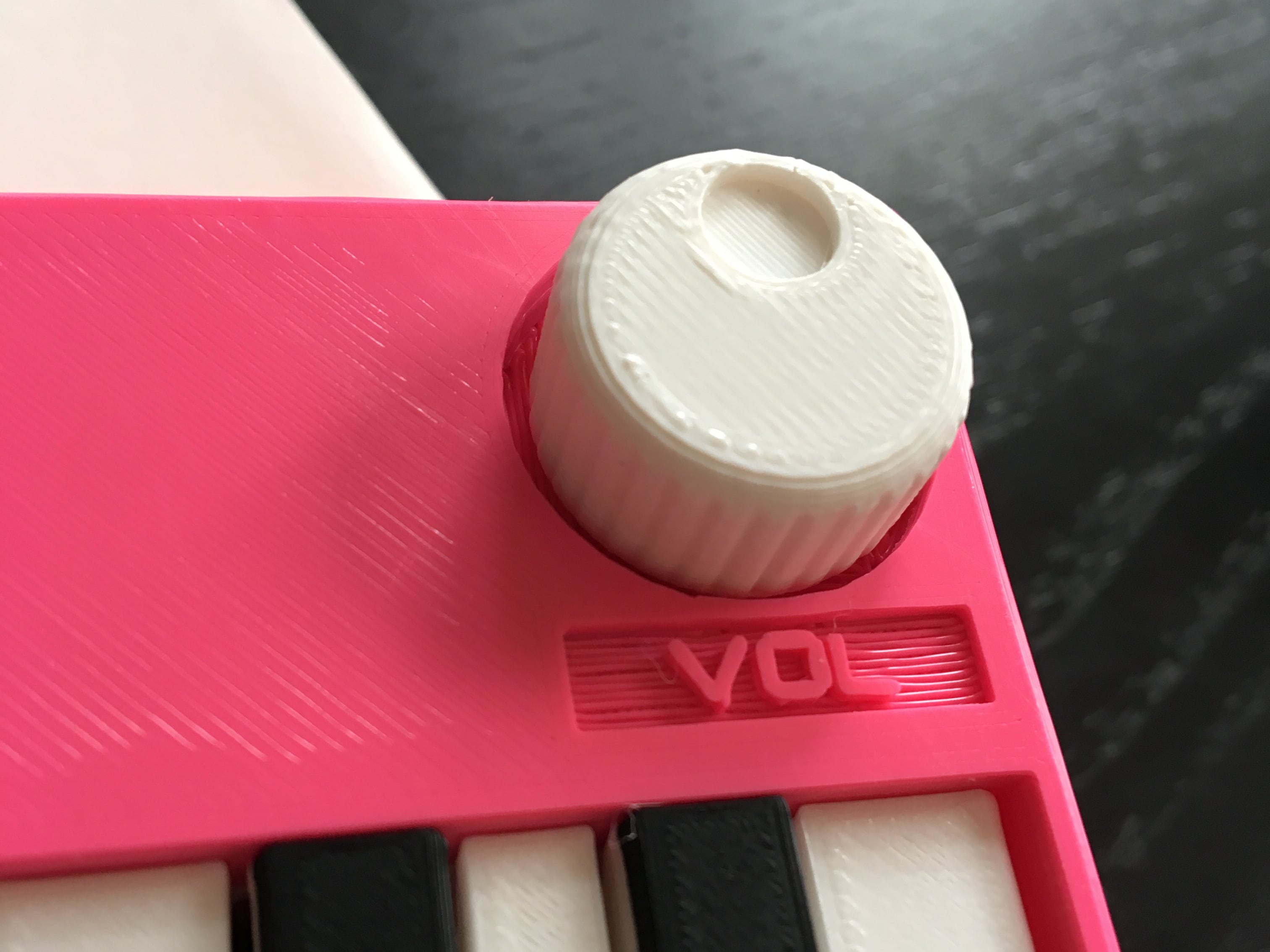
The volume knob's code is extended from the APC's wheels, ditching the spokes and subbing a brodie knob for a dimple.
Switch clutch

Also borrowed from the APC is the switch clutch, which straddles the on/off power switch's actuator and exposes it outside the enclosure as a cute little grip.
To aid printing, a built-in support props up the grip and snaps off when done. And to aid assembly, the piece is vertically symmetrical, so it doesn't matter which side you put in top vs bottom.
Get (or make!) your own
The Oskitone Scout is available now for purchase, either assembled or as a DIY electronics kit:
- Buy the Scout Synth
- Buy the Scout Synth DIY Electronics Kit
The DIY Kits can come with the 3D prints included, but folks with access to 3D printers are more than welcome to print their own! The Scout's 3D models are on Thingiverse: https://www.thingiverse.com/thing:4933700
All code for the Scout is Open Source and under the Creative Commons Attribution/Share-Alike license: https://github.com/oskitone/scout
What's next?
More keys, different wave types? Polyphony? MIDI? Maybe! We'll see!