Chord Synth
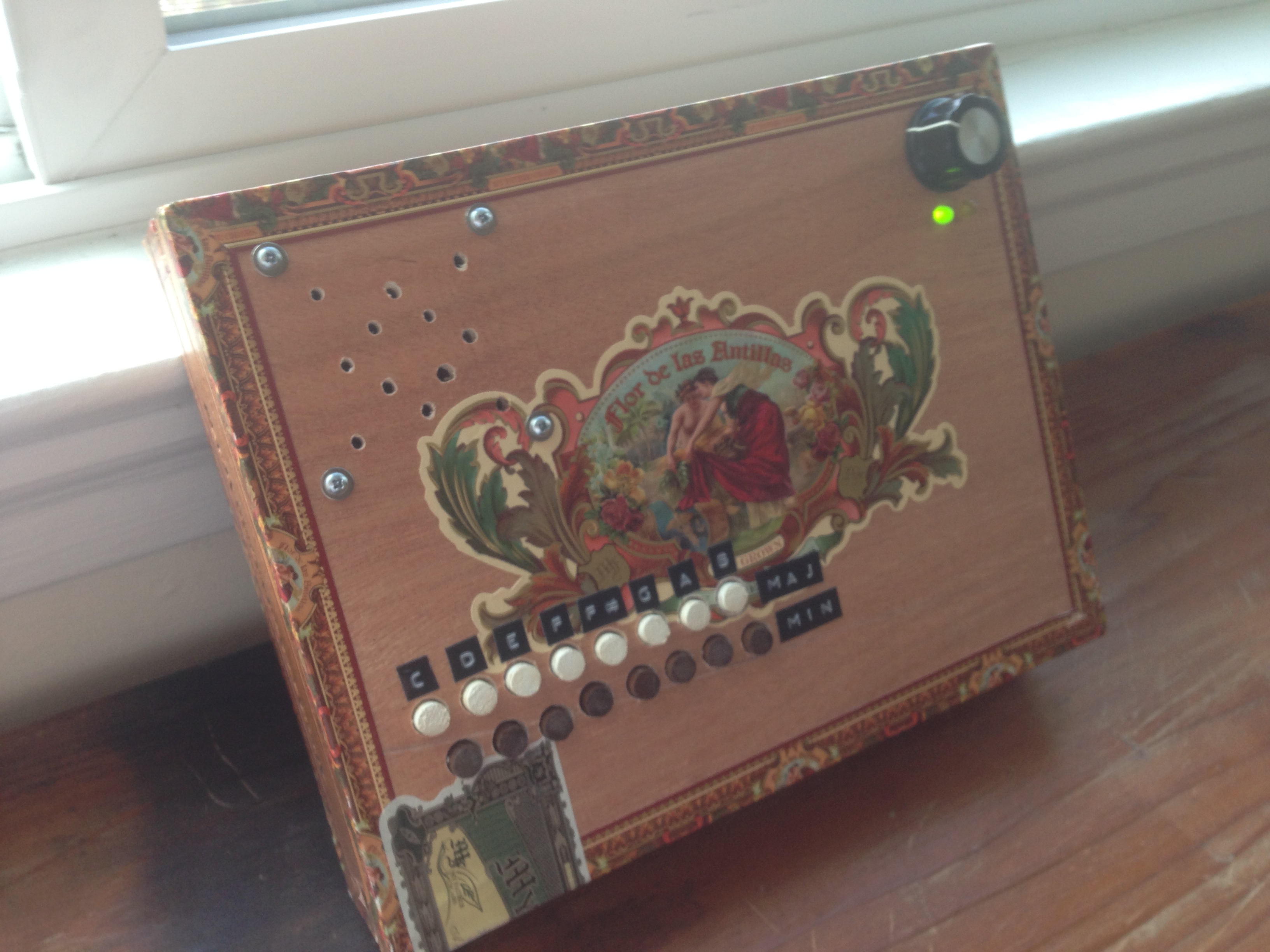
Inspired by a chord organ I had in high school, my 'chord synth' is a lo-fi analog interpretation with twelve oscillators, sixteen chords, and a wild jungle of routing jumper wires.
Organization
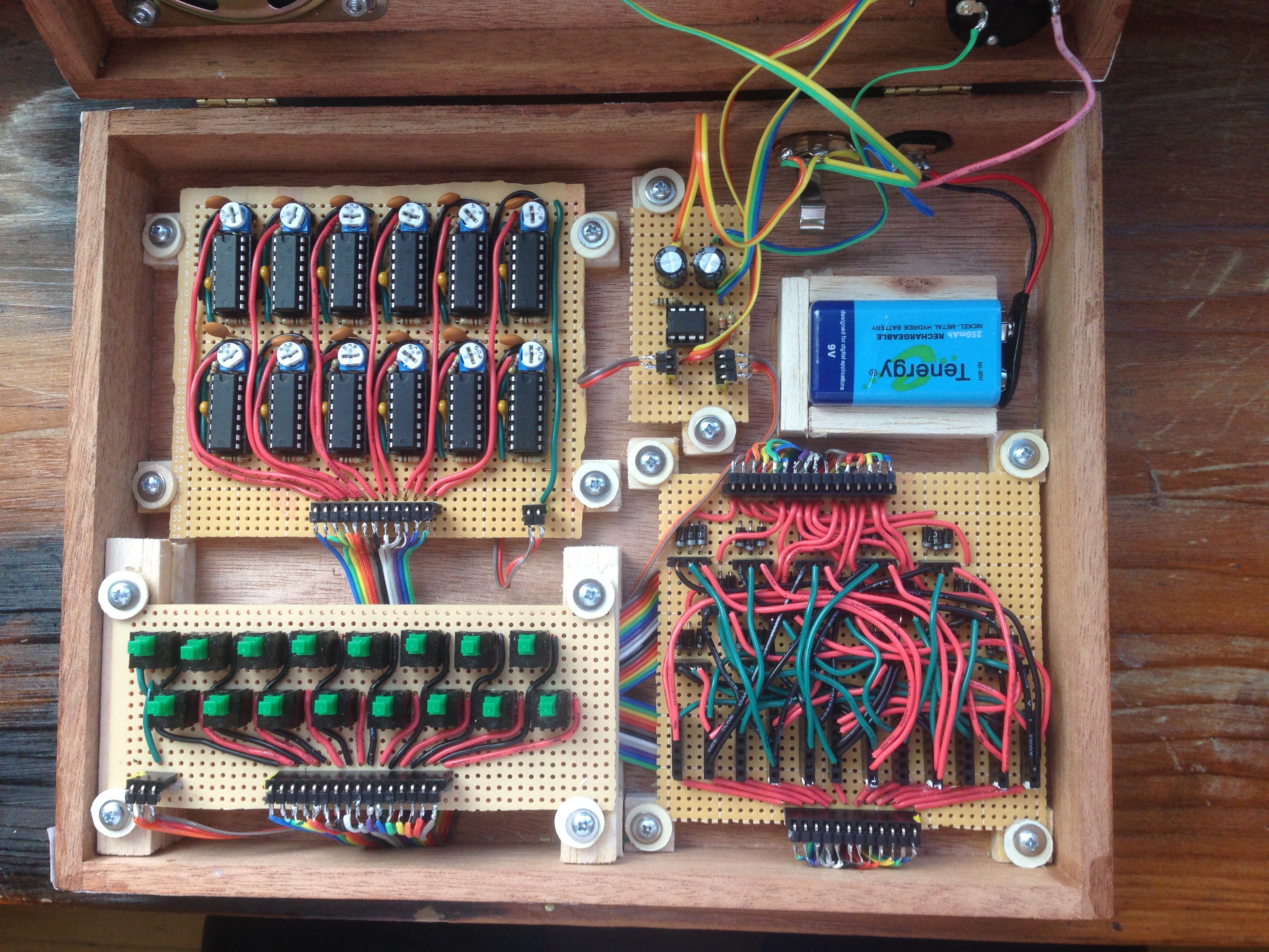
The internals try to follow the principle of single responsibility. Counter-clockwise from top-left in the photo:
- An oscillator board for the notes
- A buttons board for user input
- A router for connecting each button to its three notes
- A "chassis" board for the amplifier and its volume, battery, and other components that are connected directly to the cigar box
Each board has input and output header pins and is connected to its siblings with ribbon cable.
Board 1: Oscillators
Oscillation is "movement back and forth at a regular speed". In electronic circuits, that movement is of a voltage, and tuning its timing and applying it to a speaker results in an audible frequency: a note!
So the heart of the this instrument is twelve oscillators, one for each note in a complete octave starting at C#: C#, D, D#, E, F, F#, G, G#, A, A#, B, C
Why so many, instead of just one? The answer is polyphony: with one circuit per note, each can be played at the same time. Obviously, since a chord is comprised of multiple notes, a monophonic (one note at a time) solution wouldn't do.
Oscillator circuit

Borrowed from an 80s toy called the Magical Musical Thing, each oscillator circuit is based around a CD4049 Hex Inverter.
Like its name implies, the CD4049 has six inverting logic gates. If you give it a positive voltage (aka 1), it returns ground (aka 0); give it 0 and it returns 1. If you daisy-chain an odd number of inverters, they loop forever and make what's called a ring oscillator.
The board rigs up 12 of these:
- Power for each CD4049 is provided by the red wires, which are connected by ribbon cable to the router board
- Three of the 6 inverters on the CD4049 make a square wave, tuned by a 5k trimming potentiometer and a fixed capacitor
- The other three inverters make a simple amplifier
- When any oscillator is on, its output is summed through a mixing resistor to a common output in the green wire
I/O
(from left to right)
- 12: discrete powers from router
- 2: summed oscillators, ground
Board 2: Buttons
Inside and I/O
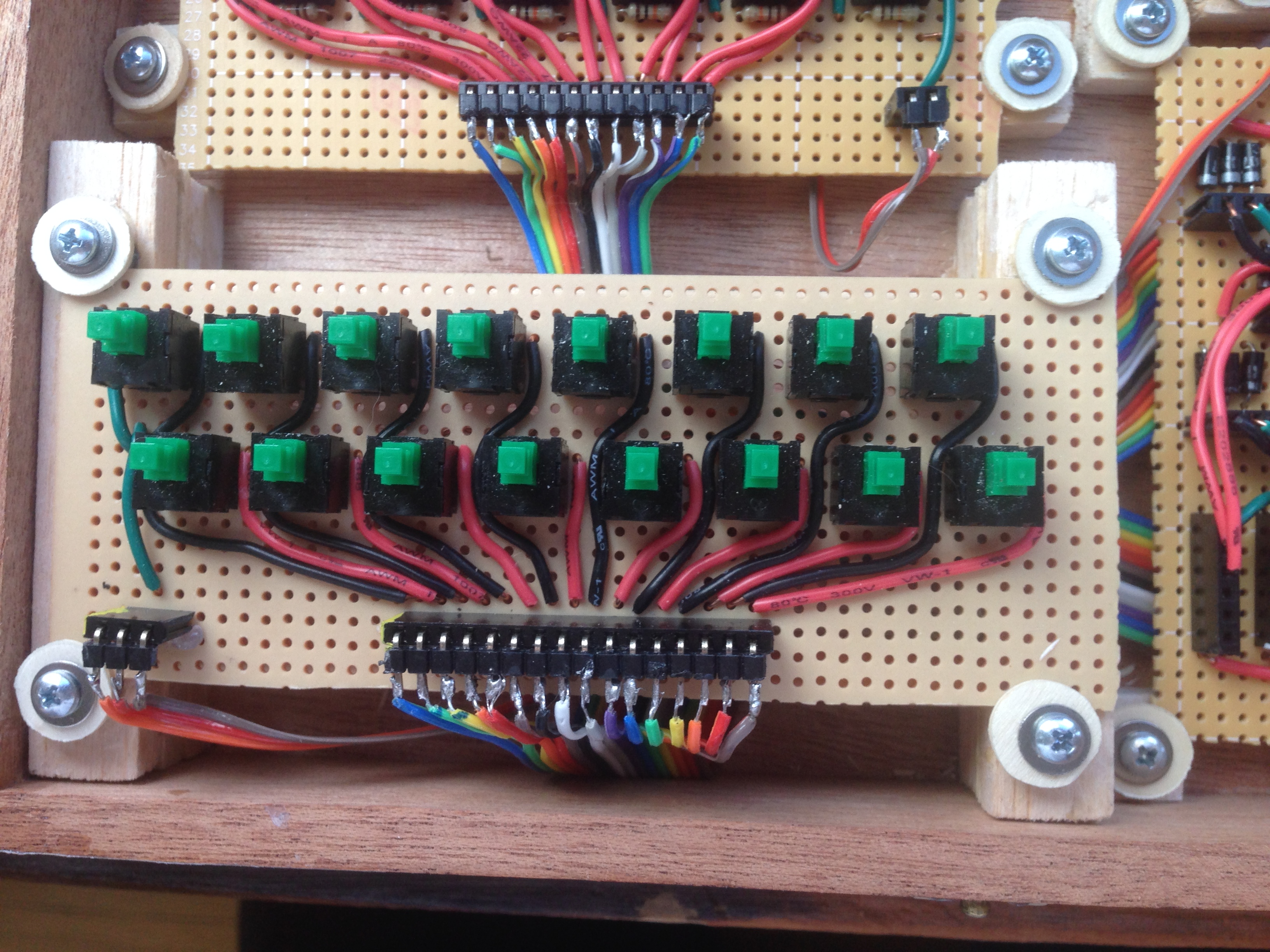
The buttons are DPDT, Double Pole Double Throw. One pair connects power to an output pin for the router. The other connects power to a "playing" status LED.
- 3: power, ground, "playing status"
- 16: chords to router
Outside
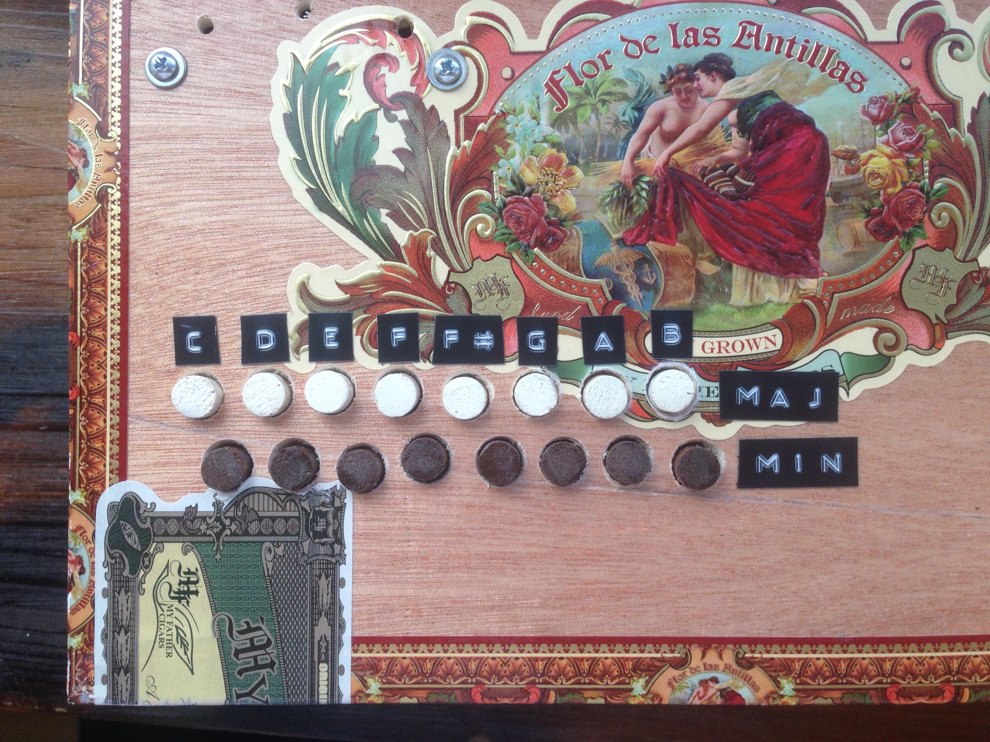
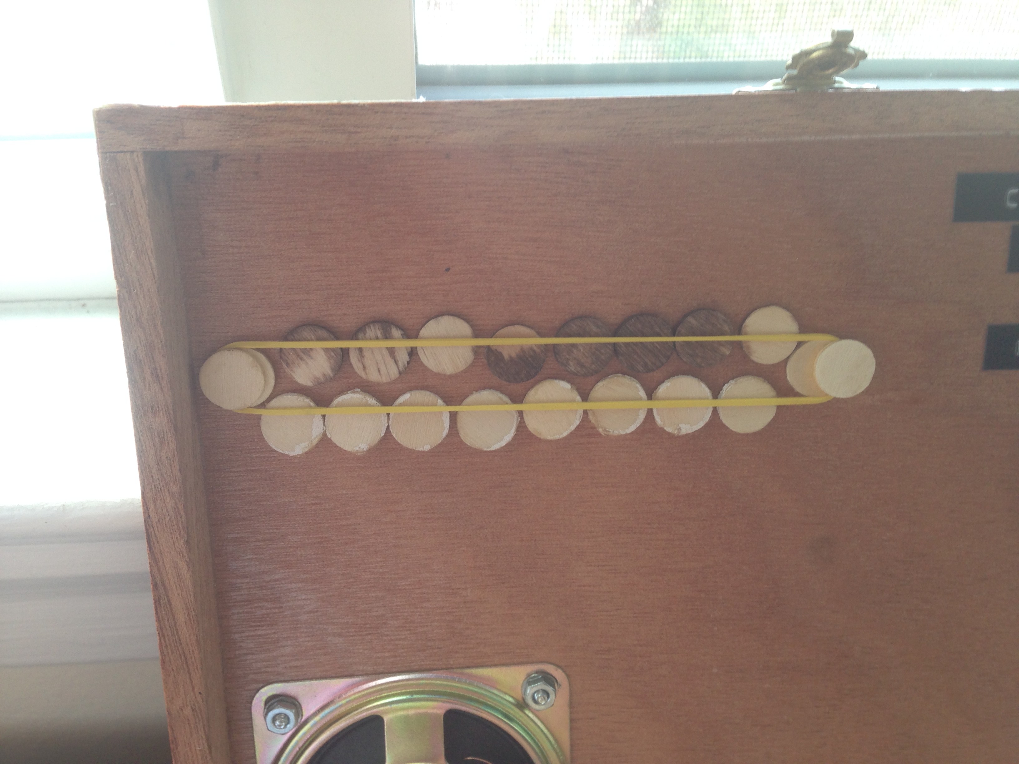
The buttons are pressed indirectly by means of overlays: cut, sanded, and painted dowels loosely fastened to the chassis by rubber band.
Aside #1: Practicality
The twelve notes generated by the oscillator board can be exhaustively combined to play all possible chords, but for simplicity I pared the options down to just the chord progressions of the keys that I like to play in:
| I | ii | iii | IV | V | vi |
|---|---|---|---|---|---|
| C Major | Dm | Em | F | G | Am |
| D Major | Em | F#m | G | A | Bm |
| E Major | F#m | G#m* | A | B | C#m* |
| G Major | Am | Bm | C | D | Em |
| A Major | Bm | Em | D | E | F#m |
( Asterisks denote casualties of scarcity. :( )
That sums to 16 chords via 16 buttons: C, D, E, F, F#, G, A, B; with rows for major and minor versions.
Aside #2: Technicality
Musicians will object that each chord is not necessarily in root position -- the chord triad notes of root, third, and fifth will be arranged arbitrarily, depending on oscillator availability. For example, its C Major's notes go E (third), G (fifth), and then C (root).
Because satisfying the desire for each chord to always have its root be the lowest note would increase the oscillators required from 12 to 20, I found it was an easily allowable quirk of the instrument to not have "nice" chords and to instead enforce its own inversions.
Board 3: Router
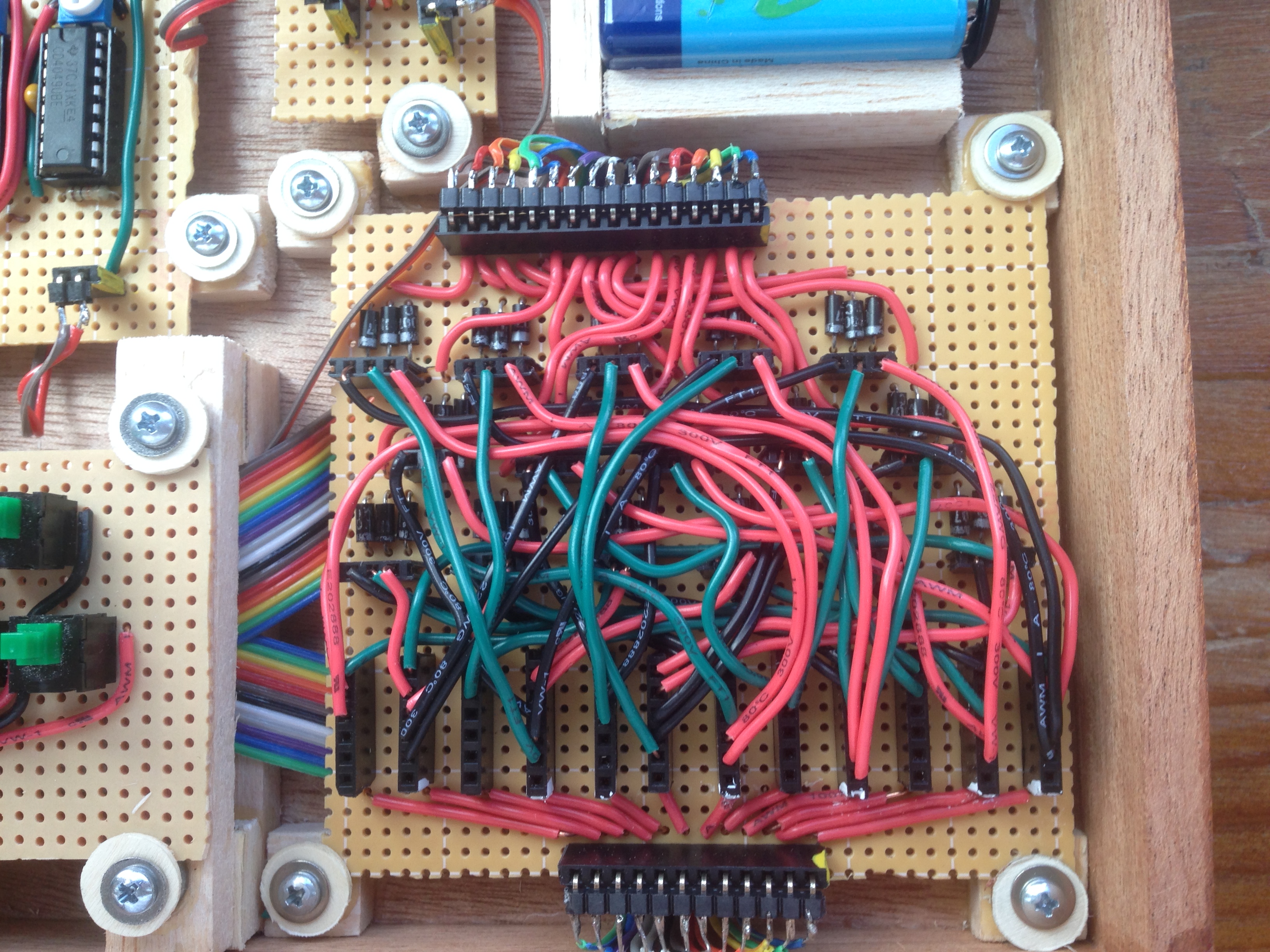
This was a crazy thing to make and looks like spaghetti, but all it really does is connect power from the buttons to the oscillators.
- The ribbon cable at the top is from the buttons board. Each of its pins represents one chord and will carry voltage if the user presses its respective button.
- That pin's voltage is split across three diodes to prevent bleed and fed into a horizontal 3-pin female header.
- From there, color-coded jumper wires connect one-way power...
- Black wire = root
- Green wire = third
- Red wire = fifth
- ...to a vertical 6-pin female header, which serves as a collecting power bus for each oscillator.
- And the ribbon cable at the bottom takes that power to the oscillator board.
I/O
(from top to bottom)
- 16: power from button board
- (internal) 3 * 16: button -> chord
- (internal) 6 * 8: chord -> oscillators
- 12: power to oscillator board
Board 4: Chassis
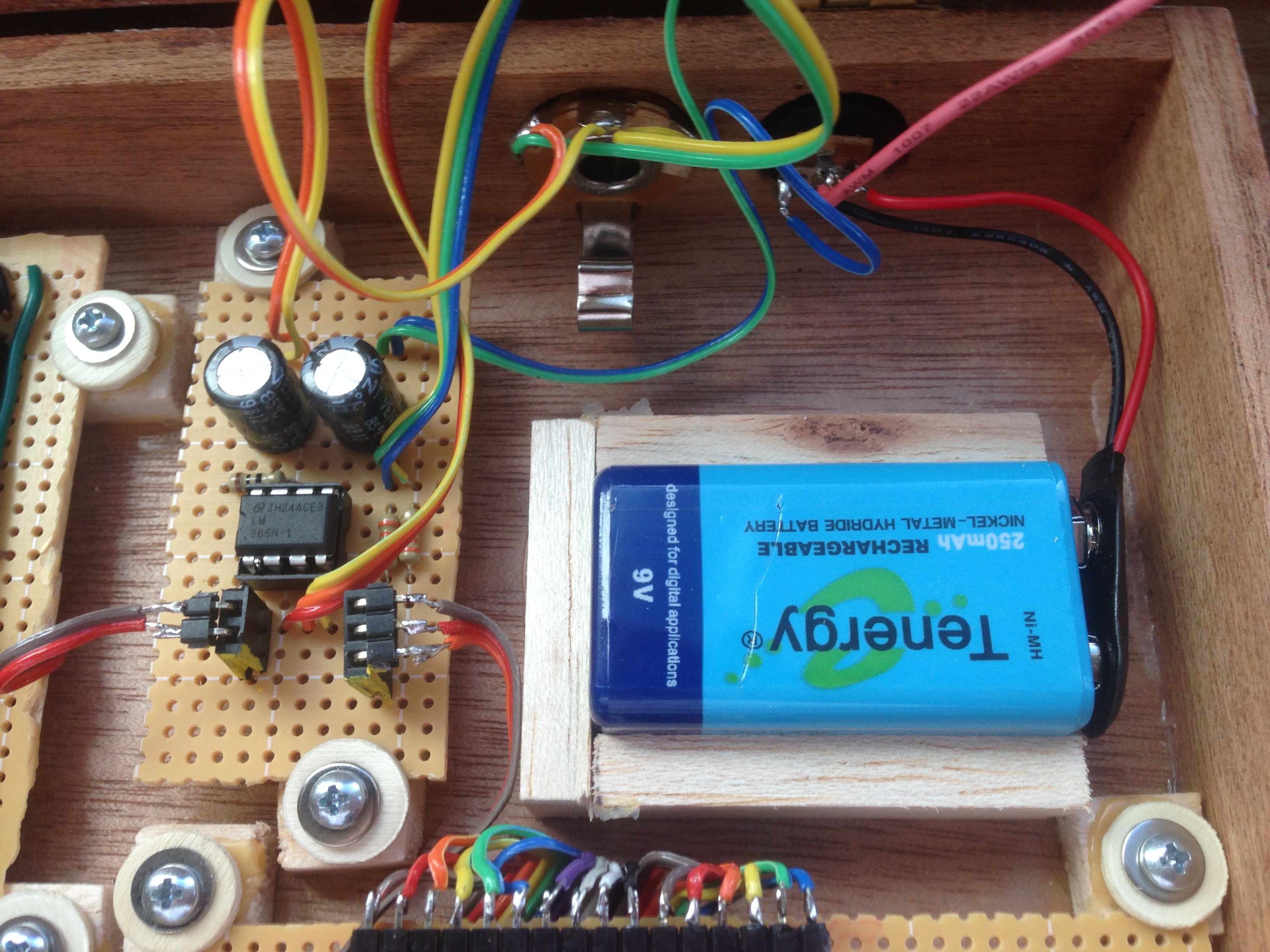
Okay, so this one isn't exactly observing the single responsibility principle, but I found it helpful to lump them all together: anything that the other boards aren't doing, this one should do. This meant that this board was the arbiter for power, ground, and anything directly attached to the chassis.
On the left, a simple LM386 amplifier makes things loud for the speaker (not pictured) or the mono 1/4" jack. When a cable's plugged into the jack, it conveniently switches off the built-in speaker.
On the right, 9 volts are supplied with the built-in battery or with a "wall wart" -- 9v is the voltage of most guitar pedals so adapters are super common.
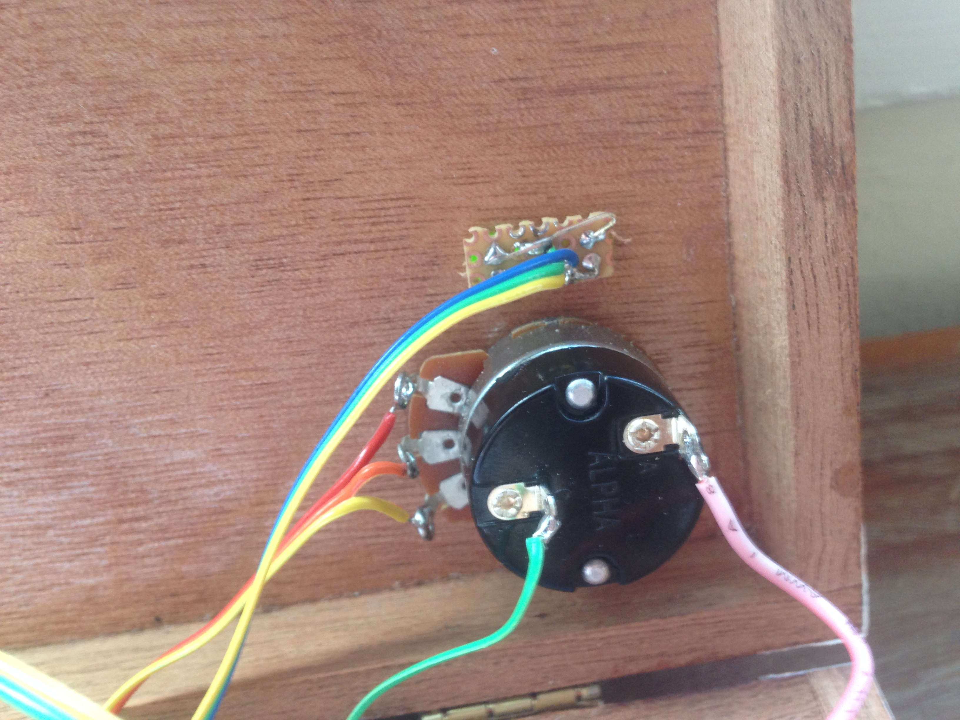
Fastened to the lid, a 10k potentiometer with switch does double duty of setting volume and toggling power and two LEDs indicate statuses for "On" and "Playing" (from the buttons board).
I/O
(clockwise from top left; direct = connected directly to board without headers)
- (direct) 2: audio output and ground to jack/speaker
- (direct) 2: power (via switch on volume potentiometer) and ground
- (direct) 3: "on" LED power, "playing" LED power, and ground
- 3: power to, ground to, and "playing" status from buttons board
- 2: ground to and summed output from oscillator board
Final product
Chord SynthFootnotes
0:
C# was an accident. It was just the lowest note I could get with the components I had on hand.
1:
Admittedly, because I'm amplifying the summed output later, I could have had each chip serve as two oscillators. In practice, I didn't like the layout and having one chip per oscillator was a simpler mental model for me to wire up.