Hello, F0
Say hello to the F0!
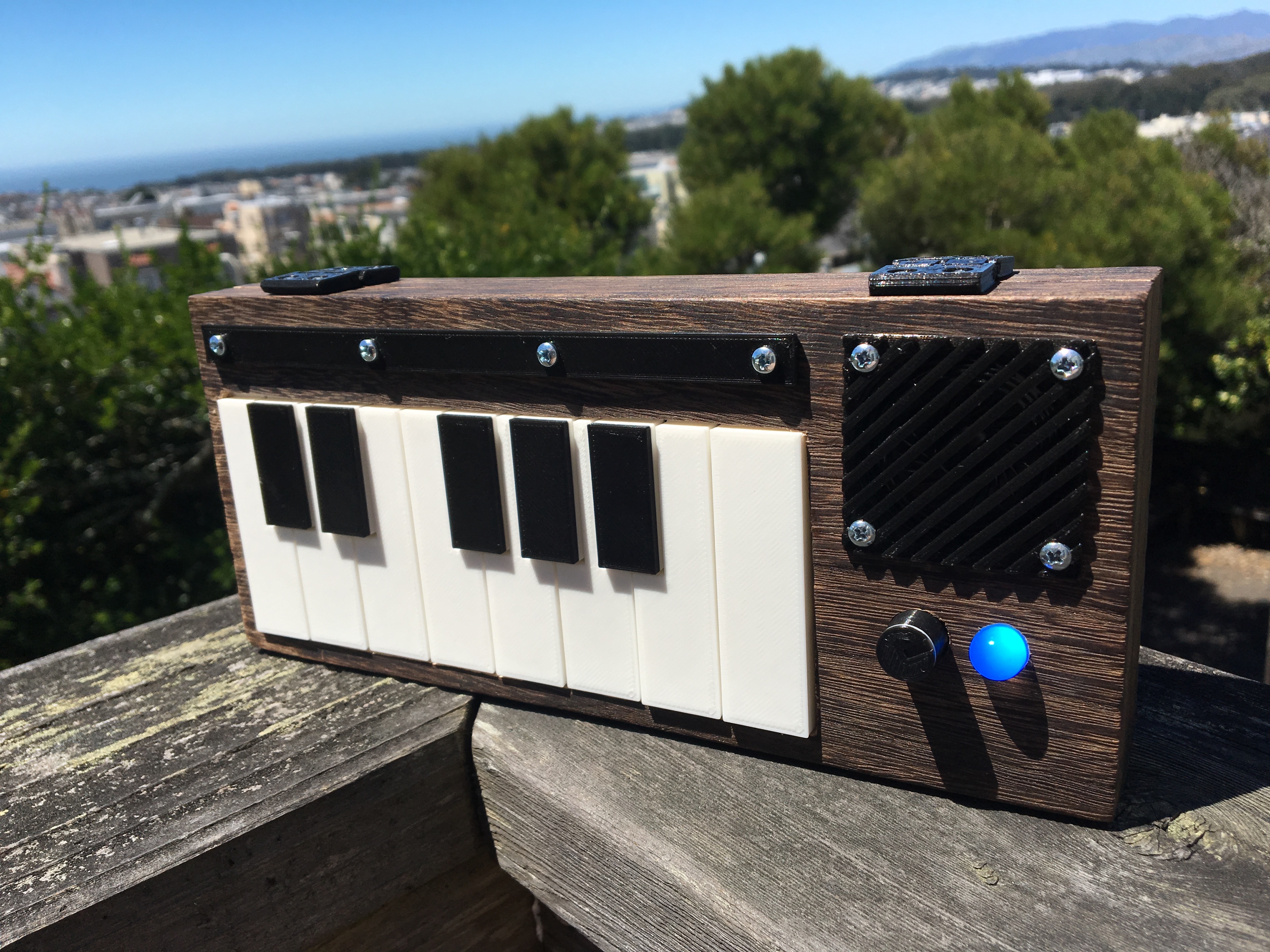
The F0 is a minimalist, analog, square wave synthesizer with chunky 3D-printed piano key overlays, 9V battery power, and a “Feathergrain” (from which we get the F in F0) box enclosure.
Because space inside the enclosure was tight and I wanted mostly just to validate a new button layout design, it is admittedly a very spartan Minimum Viable Product (MVP), but it sets a nice baseline for later iterations.
Quick overview

The heart of the F0 is a Voltage Controlled Oscillator (VCO) from a CD4046 chip. A VCO, as its name suggests, is a machine that creates a frequency determined by some input voltage. Here, a 9v battery feeds a 5v regulator to create a constant reference voltage, which is then dispersed across buttons, diodes, and trim potentiometers (13 of each) to make voltage dividers. The potentiometers tune each note, the diodes prevent the notes’ voltages from contaminating each other, and the button switches ensure that the voltage only passes when the user intends for the note to be played.
The F0 only has one VCO, which means it can only play one note at a time and is therefore a monophonic instrument. (In contrast, the POLY1 I made awhile ago is polyphonic and all of its notes can be played simultaneously.) While there’s only one octave of keys from C to C, the tuners support five full octaves.
(For more info on the chip and its VCO capabilities, read this Logic Noise article on Hackaday.)
Key buttons
Manually laying out and soldering a dozen to a couple dozen of those voltage divider circuits is a painstaking and error-prone endeavor, so the first task was to design a Printed Circuit Board (PCB) to make it easier.
I envisioned a modular system that would allow daisy-chaining any number of PCBs together to sum into a desired number of notes. Since each board wouldn’t know where in the musical scale it was, its layout must be agnostic to disposition; the same position should serve natural/accidental/white/black keys equally.
If that weren’t enough, I also imagined that the same system could be used for both monophonic and polyphonic instruments. As such, the buttons are on a separate PCB from the diodes and tuning potentiometers I described above.
Here are the fabrication previews of what I came up with for the tuning PCB (top) and buttons PCB (bottom):
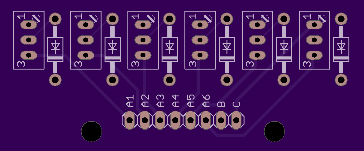
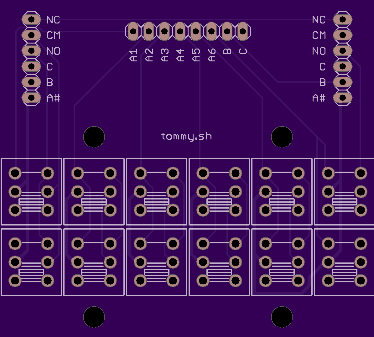
You can see that the header pins at the top and bottom of the two boards mate, and the horizontal pins on the buttons PCB mirror to match any siblings.
The A, A#, B, C pin labels basically denote potentiometer pins. The NC (Normally Closed), CM (Common), and CO (Commonly Open) labels are for the switches themselves, though my understanding in the design was incorrect so, for now, they’re unused cruft.
The 2x6 grid of rectangles below the pins is for the note buttons; the top row is for accidental notes and the bottom is for naturals. I haphazardly decided there should be 6 columns of notes.
(While I was at it, I made another version that used a different kind of button but observes the same chaining mechanisms. I’m hoping this will be used in the F1…)
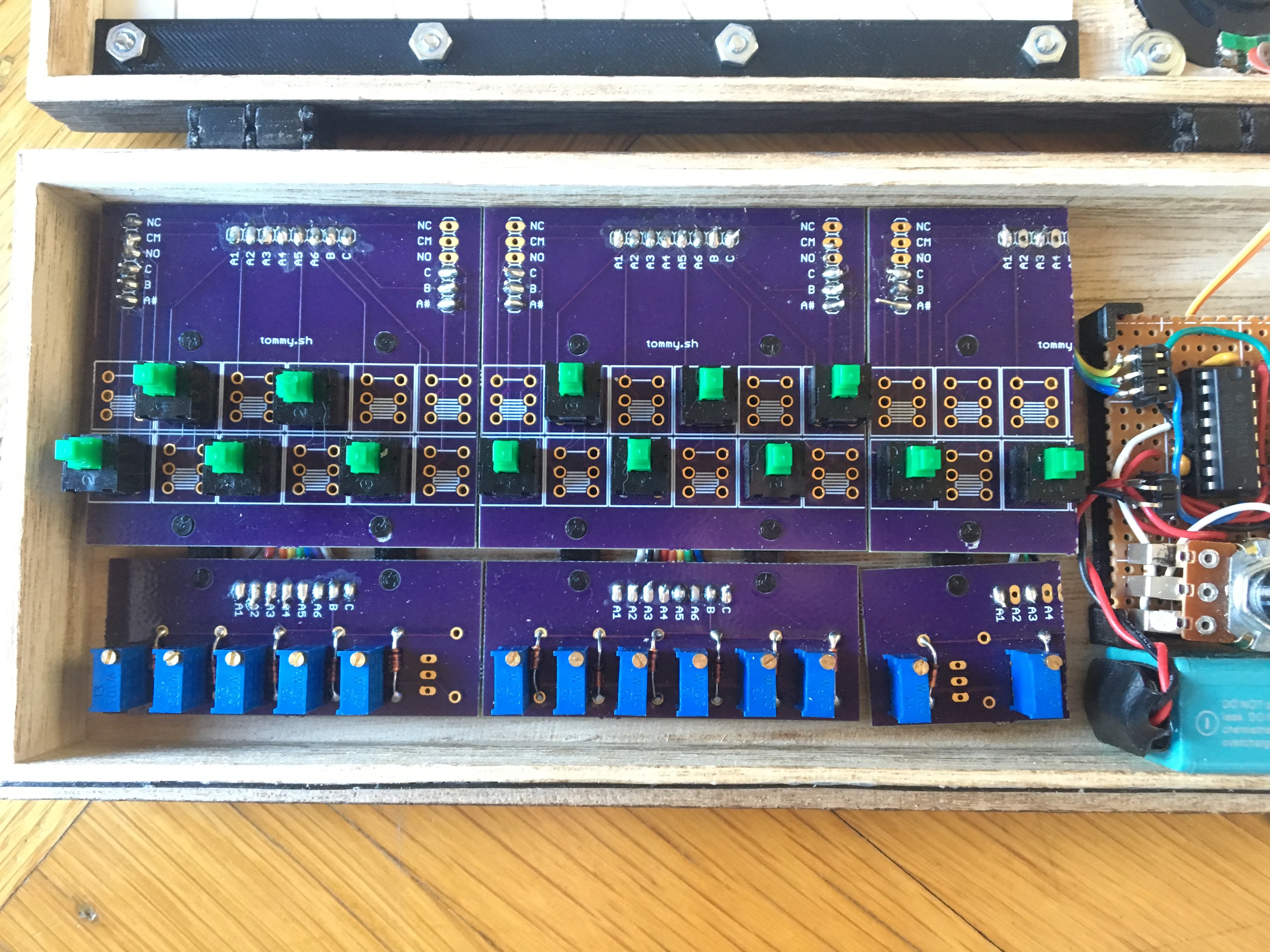
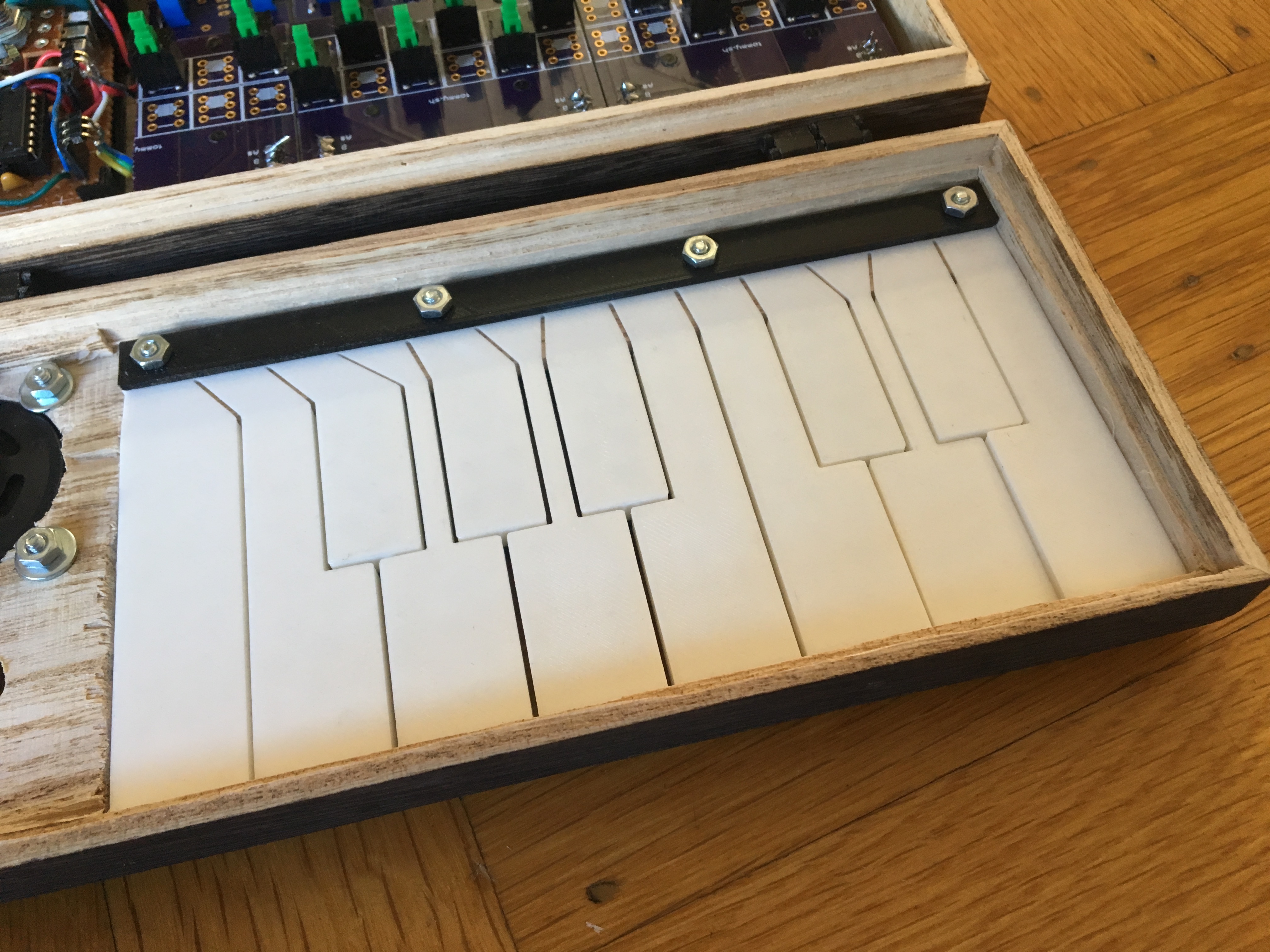
So anyway, the F0 uses two and half of these PCB combos. They’re held together and under their respective keys with a 3D-printed cradle support.
Lessons learned:
- This PCB system takes up way too much space. It’s basically ⅔ of the enclosure’s floor space, which is not acceptable aesthetically (the PCBs are cool but mostly repetition -- they shouldn’t be the machine’s internal focal point) nor practically (I want more room to do other stuff!)
- Too much of the impressive parts of this system like the 3D-printed supports or the ribbon cable connections aren’t visible and so can’t be admired when the enclosure is open. I am of the opinion that hard work should either be recognized or obviated.
- The horizontal daisy-chaining isn’t useful at this small scale. If an MVP piano has a full octave of notes, so should each individual board.
- If I ever expect anyone else to do this, I need to make the assembly much simpler and cut out as much fiddly ribbon cable soldering as possible, even if it means the boards aren’t as modular as I’d intended
Buttons, meet keys
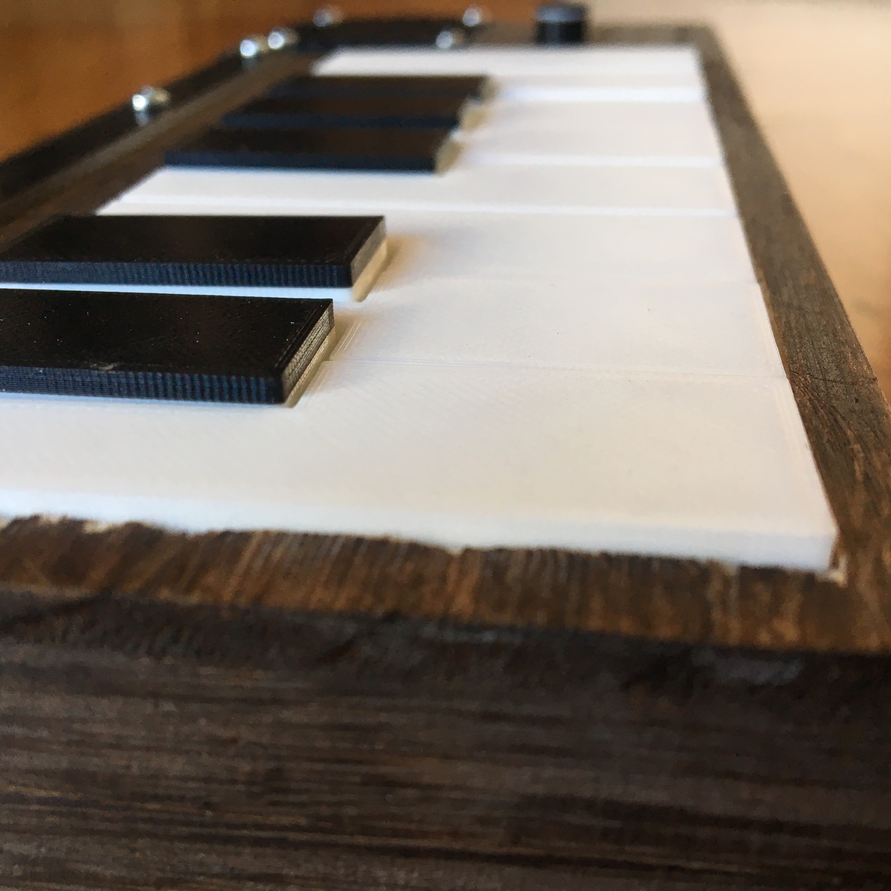
With the buttons in place, the next step is to lay some key overlays on top to make the experience closer to that of a real piano. I explored a couple different mounting options, but, for the F0, the overlays are bolted into a rectangular window cut into the top of the enclosure. When the lid closes, they simply sit atop their respective buttons.
(Designing these key overlays was a lot of fun and something I’ve been kind of noodling on outside of software for some time. A separate writeup is in the works.)
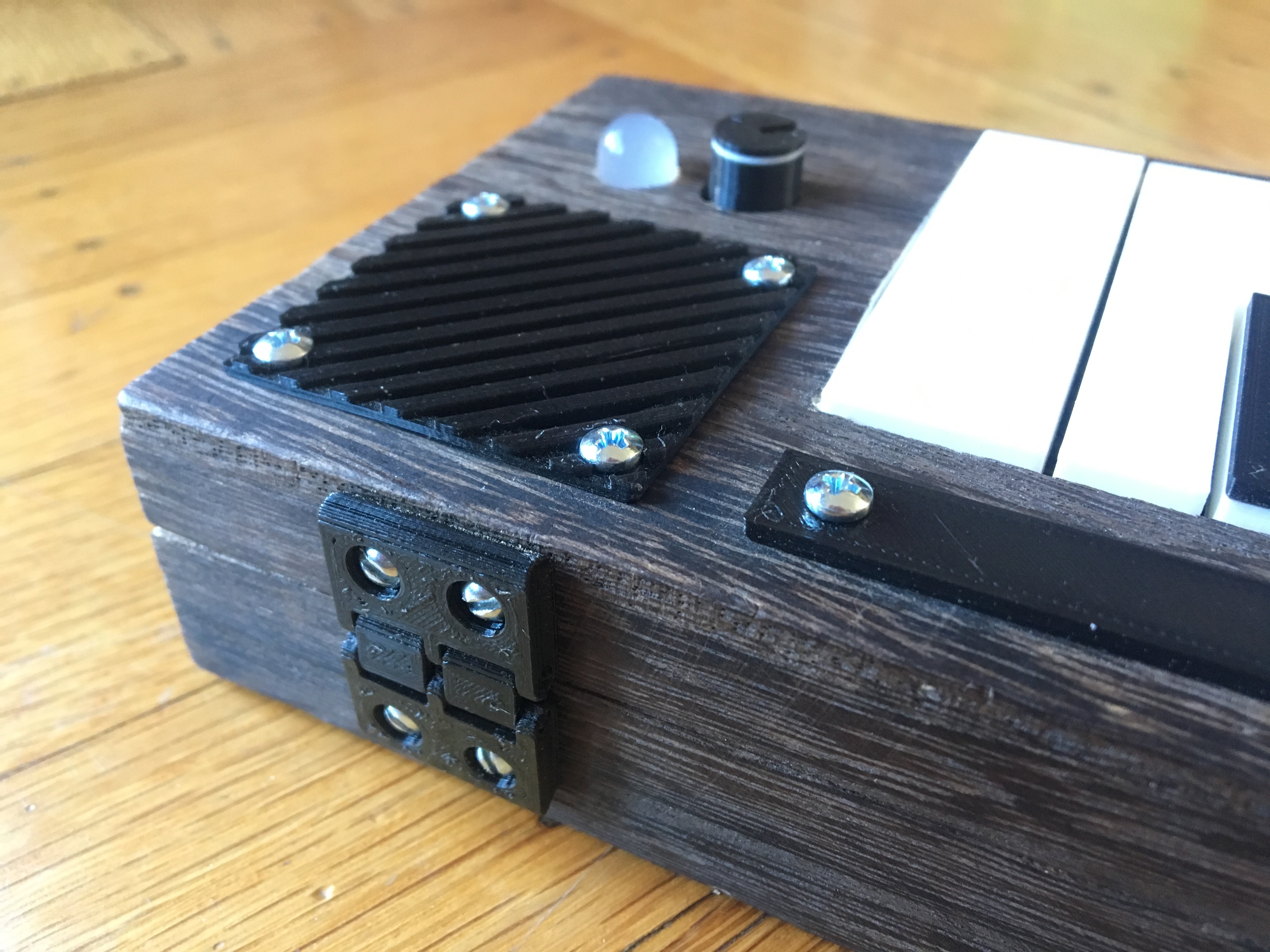
The rest of the electronics
So the buttons provide tuned voltages to the VCO, which makes sound that’s amplified by a simple headphone amplifier, and that’s sent to the speaker. A switched potentiometer plays dual roles of setting the volume and turning the machine on and off, and a thick 10mm LED makes sure the user knows when it’s on.
The PCBs were professionally fabricated by a third-party service, but the rest of the circuitry is on perforated board. Thus the discrepancy in board color and style.

(One problem I didn’t totally figure out for this project is what I’ve learned is called “VCO frequency pulling/pushing”: changing the volume inadvertently changes voltages and consequently shifts frequencies, making the instrument subtly musically inaccurate.)
Enclosure
The store-bought box enclosure gets the job done but is a glaring concession in what would otherwise be an entirely custom piece of work.
Lessons here:
- Light wood is easy to cut but is too brittle and breaks too easily. It just feels cheap.
- Too many holes (most noticeably, the giant window for the key overlays) make for a lousy speaker cabinet. Even if the speaker were better, there’d still be no low end
- I wanted the volume knob to have a flush exposed height with the LED, so it’s not mounted to the enclosure like I’d typically do. Instead, it’s mounted to the circuit board and the enclosure top has a knob-sized hole to fit over top. This makes the hinged lid difficult to close
- Designing my own hinges really felt like reinventing the wheel, but that’s okay!
Down the line, I’d like to make my own enclosures. Not yet though.
Getting 3D
I had to model the key overlays, PCB supports, speaker grill, and enclosure hinges, so I might as well throw them all together.
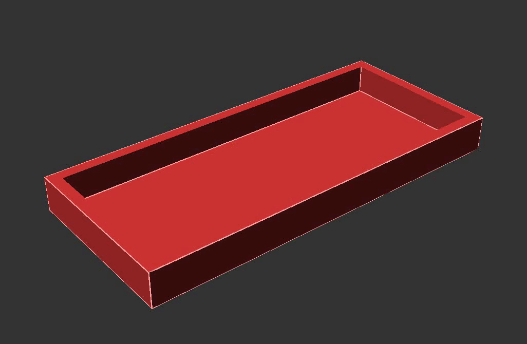
A cool side effect of having the full instrument as a 3D model is that I can use it to make a stencil for cutting holes on the real enclosure.
What does it sound like?!
Here’s a video of the F0 getting tuned up and playing a haphazard blues scale.
Hello, F0In the end, given the F0 is an MVP w ith limited musical use, I don’t think I’ll try to sell it and will instead keep it around for reference and plunking. It’s got its imperfections, but I’m pretty happy with how it came out.
Stay tuned for more!